This thread has been locked.

If you have a related question, please click the "Ask a related question" button in the top right corner. The newly created question will be automatically linked to this question.

TPS552882: Component Failure Over Time

Part Number: TPS552882

Tool/software:

Hello TI,

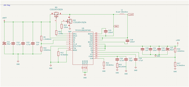
I have a design for the TPS552882 to take a voltage input of 20.0V to 33.6V and output 20.0V. The current draw of that 20.0V output does not pass 2A. This regulator is the used to power 3 stepper motors controlled by a separate board. 

Upon initial testing, everything seemed to be functioning, with the regulator outputting a constant voltage under load. It was used for about an hour straight with varying load and voltage inputs ranging from 20V to 25V from a benchtop power supply. 

After about an hour of operation, the device was powered off. Trying to power it on again shortly after, there is 0V on the output. 

Using a second identical board, similar behavior was noticed, but the failure mode was different. Again, the board proved to initially be functional for about an hour of intermittent use. Unlike the first board, this one was powered by a 30V battery. Similarly, it was working just fine until it was powered off and won't power on again. However, this one is stuck outputting ~1.7V. In this case, the regulator IC seems to be drawing ~2 watts and is heating very quickly.

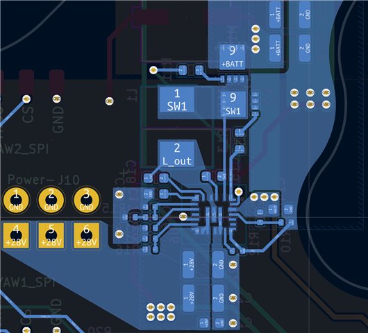
I have attached the schematic and layout for review and feedback. Any suggestions would be much appreciated. Thanks!

  • Hi Andy,

    Thank you for reaching out. Can you help provide waveforms of SW1, SW2, inductor current(most important), and Vout? I want to check the working condition.

    I think there might be two reasons:

    1. Loop stability problem. We can check your inductor current waveforms to verify. Recommend to change L1 to 4.7uF. Please provide part number of C21-C33 for loop calculation,

    2.Drive resistor is too large. This may cause shoot through. Please change to 0ohm.

    Other suggestion:

    1. Change R10 to 200kohm in case EN voltage is lower than threshold.

    2.Recommend to add RC snubber in SW1 and SW2. 330pF+2.2ohm.

    3.What is saturation current of inductor? 

    As to ,layout, please refer to the layout guideline1376.TPS55288 Layout Guideline (Rev B).pdf

    1. AGND PGND is not seperated.

    2.No enough vias for thermal. You can test device temperature.

    3.Input capacitor and output capacitor are too far from power loop. Recommend to add a 0.1uF 0402 cap in input loop and output loop. See attached.

    Regards,

    Mulin