This thread has been locked.

If you have a related question, please click the "Ask a related question" button in the top right corner. The newly created question will be automatically linked to this question.

LM74700D-Q1: Concerns to be addressed

Part Number: LM74700D-Q1

Tool/software:

Hi,

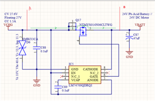
I am using LM74700D-Q1 in my design as below. The circuit is used to protect my charging circuitry from any reverse current/voltage that may had caused by the battery or back emf of the motor.

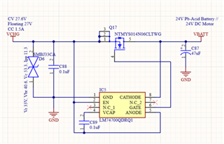
Following the datasheet, with my CC of 1.5A I had chosen NTMYS014N06CLTWG as the N-Ch FET for the circuit. Rdson 15mohm @10Vgs & 21.5mohm @ 4.5V.

Few concerns that I have listed below:

1. Is it correct to use my CC 1.5A as the I_load nominal in this case? 

2. During taper current / Floating Voltage mode, will the low charging current (eg 50mA) still be able to pass through the circuit?

3. Also, with 1.5A and chosen Rdson of 21.5mohm max, I will never reach the full conduction mode of 50mV. Is this a concern?

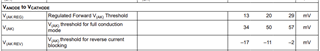
4. The reverse current only detected at -11mV, this means with Rdson of 21.5mohm it translates to 0.5A. Anything less than 0.5A reverse current is still going to backfeed my charging circuit? I afraid that would damage my components.

5. Currently I'm connecting my ideal diode before my feedback node to the charging circuitry (the FB node use to detect battery voltage). Please advise if this is the correct way to do this. My understanding is that if I were to put the ideal diode after the feedback node, then my charging IC at the startup will not detect any voltage thus it will not turn ON charging.

Thank you for your time.

Best Regards,

Amirul

  • Hi Amirul,

    Welcome to E2E.

    1. Yes, 1.5A is the correct number.

    2. If the GATE is low, body diode of the FET will still conduct, and power path is never cutoff. 

    3. Please go through this FAQ. Device will enter full conduction mode at around (20mV/21.5mohms) of load current.

    (+) [FAQ]: Ideal Diode Controller or ORing Controller gate voltage is lower than expected - Power management forum - Power management - TI E2E support forums

    4. 0.5A is the transient reverse current that will flow, there will be 0A of DC reverse current flow. LM74700D uses a linear regulation scheme to drive FET which mean the GATE voltage depends on the forward current that flows. For slow changing voltage, the forward current will decrease, and the GATE will be at lower voltage. Which means the RDS will be higher. 

    5. You can keep your feedback node at point A or point B. Since the body diode is present, power path is always present. Only thing to understand is point B is always protected from reverse polarity, hence if your FB node is to be protected by reverse connection, keep it after the Ideal diode.

    Regards,

    Shiven Dhir