This thread has been locked.

If you have a related question, please click the "Ask a related question" button in the top right corner. The newly created question will be automatically linked to this question.

TPS53688: Phase/Gain margin measurement

Part Number: TPS53688

Tool/software:

Hi,
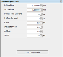
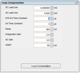
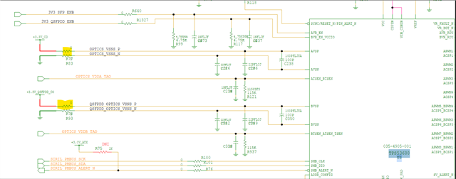
We are doing phase margin/gain margin measurement using frequency response analyser for a multiphase power circuit with output +3.3V/50A(per channel) for both the channels of the controller (TPS53688+2xCSD95515RXMR).
We are injecting the signal and measuring across 10ohm resistor in series with the sense positive line.

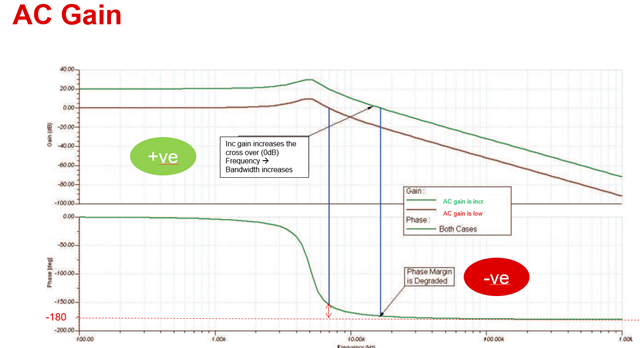
Although we are getting a proper gain curve, the phase curve is getting flat for both the channels.

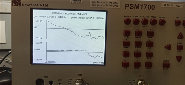
Kindly share your suggestions.

  • Hi Ujjwal,

    We don't tend to recommend relying too much on Bode analysis because it doesn't give an accurate picture for a complex non-linear system. Are you seeing any instability on Vout or switch node during transients? Oscillations in Vout during a transient or jitter/noise on PWM and switch are more reliable indicators of system stability. 

    Thanks, 

    Ryan

  • Hi Ryan,

    Thanks for the update. Phase/gain margin seems to be coming fine on another output having same controller. Please see below graph and parameters setting for the same.

    Can you share your comments on the same, why we may be getting different phase shape for the same controller but different output voltage?

    Our major concern is we are measuring only 20deg phase margin on the problematic net which even after extreme tunning of compensation parameters is only reaching 40deg whereas the different output voltage using the same controller we are able to easily tune up to 61deg.

    Below are the loop compensation parameter values for problematic net for which we were able to reach 40deg of phase margin.

  • Hi Ujjwal, 

    Different output voltage will change the tuning significantly. One reason for this is when the output voltage changes, the caps will have a different response.

    For tuning, AC Gain will speed up the loop causing less phase margin. If the goal is slowing down the loop, you would want high ACLL, High Int time constant, low Int gain and low AC Gain. 


    For DCAP+ Devices which use a modified PI control loop,  

    - (1/ACLL) is equivalent to proportional gain

    - (Int time constant/Int Gain) is equivalent to total integral gain

    - AC Gain scales all loop compensation effects