This thread has been locked.

If you have a related question, please click the "Ask a related question" button in the top right corner. The newly created question will be automatically linked to this question.

UCC27712-Q1: Not able to achieve 100% PWM

Part Number: UCC27712-Q1
Other Parts Discussed in Thread: UCC27712, UCC25800

Tool/software:

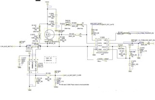
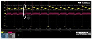
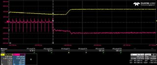
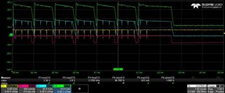
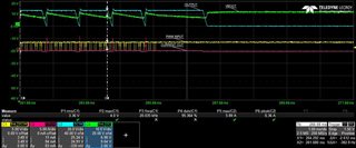
I am trying to drive a motor high side using this driver as shown in the image. The Vsys is from 21-29V. I am only able to achieve 80% with motor connected and only 90% with resistive load connected. After this the driver output is zero even with input. I tried varying the current taken by load from 1A to 0.1A but had no effect.

  • Hi Jithu,

    Apologies for the delay. Have assigned the thread to the right expert. Please allow us until end of business day tomorrow Dallas time to get back to you. Appreciate your understanding and patience.

    Best,

    Pratik

  • Initially i thought my issue was with bootstrap capacitor, so i probed around it. i can see that due to bootstrap voltage going roughly below 7.3V the system will turn off and then after it charges it again switches on(untitled the pwm is  80%).

    When the PWM goes above ~80% the the output turns to zero even when cap is at 12V as shown below. here the PWM is increased from 0-100%. RED is current through motor (or resistive load as i tried with both). yellow is cap.

    I am trying to say that the UVLO occurs when the charge in cap decreases below ~7.2V and the output turns off but at 100% even when capacitor is charged back to 12V above the UVLO the output is no present.

  • A clear image of the issue happening for resistive load.

    One more observation is that i tried increasing the duty cycle slowly from 0 to 100 and then go back to zero. i observed that after 80 to 100 and back to 80 its misbehaving but working smoothly from 0-80 and 80 to 0.

  • Hello Jithu,

    To truly achieve 100% duty cycle on the high side floating driver, there will need to be a dedicated floating bias for the HB-HS pin. The bootstrap bias method will always have some maximum on time limitation because the HB-HS bias will eventually drop below UVLO.

    Some of the behavior you are seeing on the HB bias dropping below UVLO and the HO output responding are likely related to the following. There is a UVLO delay time from when HB-HS reaches the rising UVLO threshold to when the HO output will respond. Also most of the 600V drivers including the UCC27712, have an edge triggered level shifter to minimize power dissipation in the input to floating high side level shifter. When the VDD and HB bias are above UVLO the level shifter sends fixed pulses on the turn on and turn off edges of the input signal to turn on and off the HO output. If HB is below the UVLO threshold when there is an input rising edge, the HO will not turn on. If the input continues to stay high and HB rises above UVLO, the HO will still be off, since the rising edge was missed. The HO will turn on during the next HI rising edge.

    Regards, 

  • Can you suggest a method to achieve 100% duty using floating bias? Does it involve transistor based isolated circuit?

  • Hello Jithu,

    There are simple solutions from TI targeted for isolated bias circuits. The UCC25800 and SN650x devices are small simple to use parts that have off the shelf transformers available.

    Below is a link the the products with datasheet links. The datasheets show the circuits and design details.

    https://www.ti.com/isolation/power-signal-isolators/transformer-drivers/products.html

    Regards,