


Tool/software:
Looking at the data sheet example designs for example Figure 9-4 in the datasheet
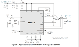
The isns and V out paths have not compensation network,
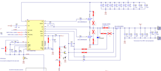
However in certain applications I see resistor added in series and a capacitor across the two paths.
For example PMP31252 Schematic
what is the purpose of these added components, is there a supporting equation to calculate the values?
What are the benefits and down sides of adding this to the amplifier? wouldn't the resistor and capacitor cause delays in the response of the circuit?
Are they still to be routed differentially ?

