This thread has been locked.

If you have a related question, please click the "Ask a related question" button in the top right corner. The newly created question will be automatically linked to this question.

UCC28951-Q1: Power management forum

Part Number: UCC28951-Q1
Other Parts Discussed in Thread: UCC28951

Tool/software:

Hello Mike,

Two output windings are connected in series. Output is regulated to 26V.

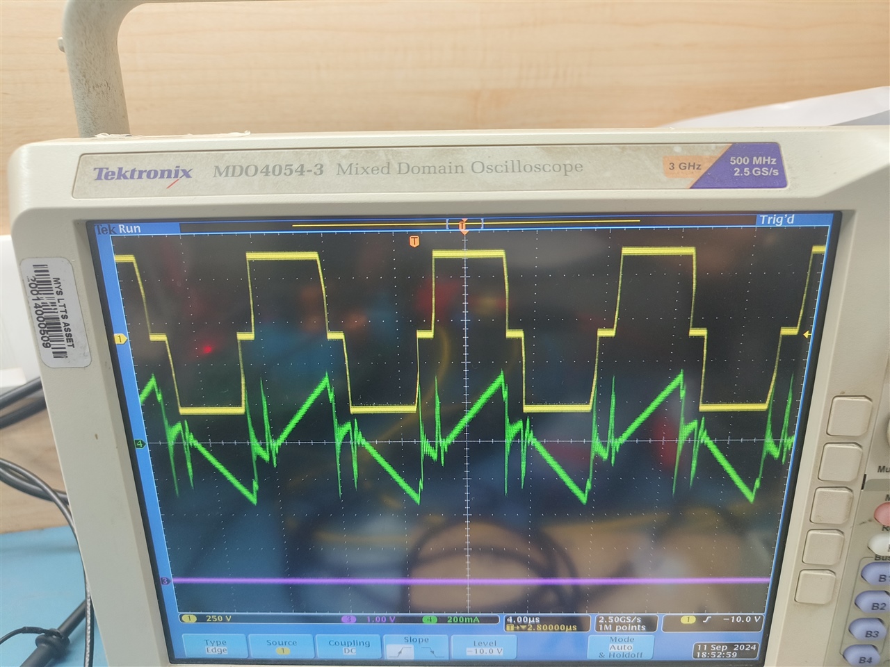
Below waveform is before it enters regulation, voltage is around 300VDC, load current: 1A

Green : transformer primary current waveforms 

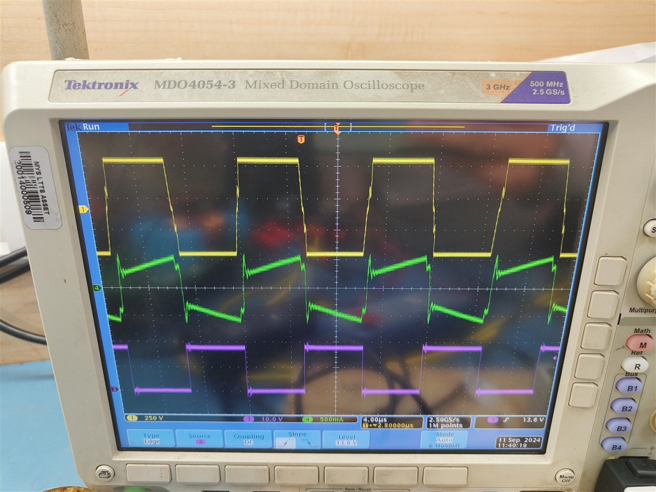
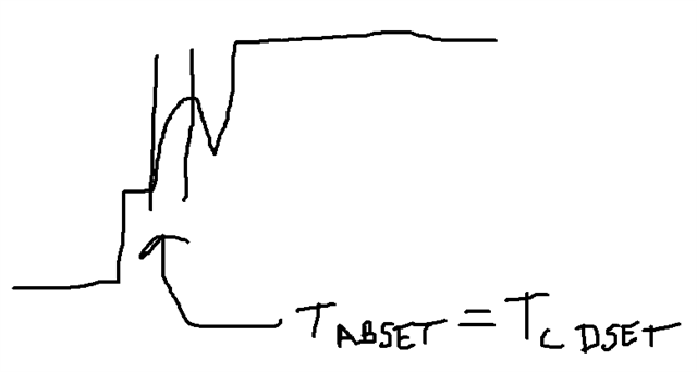
Below are current waveforms at higher voltages around 380V, 1A load, DCM mode. This is after it enters regulation. ADDITIONALLY, here, I adjust fixed delays to avoid resonant ring.

So, what happens is at higher voltages, current waveform is appearing as seen below. If I try to increase load current, let's say 3A, instability starts occurring. its tarts oscillating.

FYI, VOLTAGE loop I checked is stable upto 550VDC in closed loop.

Additionally, In Open loop i checked and loaded current upto 10A, no Issues.

  • Hello,

    Your inquiry has been received and is under review.

    Regards,

  • Hello,

    1. In your first waveform it looks like your TABSET and TCDSET is not setup correctly.

    The spikes are actually the resonant ring between the switch node capacitance and your shim inductor (Ls), leakage inductance Llk and switch node capacitance (Csw).

    The TABSET and TCDSET delays are are to long.  You need to set the delays to 1/4 the resonant frequency please note the equation is below for setting the initial delay.  

    TABSET = TCDSET = 1/(4*(*2*3.14*(Csw*(Ls+Llk)^0.5))

    I also drew a picture where this delay should be set. Your delay is just to long.

    2.  Your second waveform the transformer primary current shows that there is negative current going through your output filter inductor at light loads.  This should not be the case.  You should turn your SRs before the inductor current can go negative. 

    The UCC28951 has a DCM comparator that can be used to turn-off the SRs based on loading this will prevent negative current from building up in the output inductor.

    The following link will bring you to an application note that goes through the step by step design process of using the UCC28951 in a phase shifted full bridge converter.  There is a section on how to setup the DCM comparator to prevent negative current in the SRs and output filter inductor.

    https://www.ti.com/lit/pdf/slua560

    Thank you for interest in Texas Instruments (TI) products.  If you have a related question, please click the "Ask a related question" button in the top right corner. The newly created question will be automatically linked to this question.