This thread has been locked.

If you have a related question, please click the "Ask a related question" button in the top right corner. The newly created question will be automatically linked to this question.

TPS628301: TPS628301ADRLR

Part Number: TPS628301

Tool/software:

Hello!

I assembled a buck circuit according to the recommended specifications in the datasheet using the TPS628301ADRLR. The problem is that several units showed issues with output voltage regulation. Using the same components, some circuits provided a 3.3V output as expected, while others showed an output of 4.3~4.4V.

I noticed that the feedback voltage (VFB) when the output was 3.3V stayed around 0.5V. When the output was 4.3~4.4V, the VFB voltage was 0.7V.

I haven't been able to understand the cause of the problem yet. Could you help me with this? Is there any adjustment I might have missed?
Attached is a schematic illustration and the list of components:


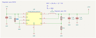
L2 = CIGT201210UHR47MNE
R20 = RC0402FR-07100KL
C10 = CL10A106MP8NNNC
R23 = RC0402FR-071M13L
R24 = RT0402BRD07200KL
C16 = CL21A476MQYNNNG
C18 = NOT


  • Hello Vinícius,

    thanks for reaching out in E2E,

    Your schematic is looking alright.

    Were you measuring the VFB voltage at the FB pin lead of the IC? Maybe the soldering of the IC pins is not properly made. Also please check the VOS and GND pin.

    Is the increased output voltage stable? Or is it ringing?

    You could also check the SW signal, as its waveform might give additional indication for the problem.

    I would also suggest to review the layout.

    Please let me know your feedback.

    Best regards,

    Andreas.

  • Hello!

    While checking the components, I noticed that the input capacitor had a lower capacitance than expected, so I replaced it with a 22uF electrolytic capacitor, and the output decreased but started oscillating.
    Then, I replaced the output capacitor with a 47uF electrolytic capacitor and added a 100nF capacitor in parallel. This significantly reduced the output oscillation to between 3.325V and 3.480V. Finally, I added a load to the output (an LED), and the voltage stabilized at 3.478V.

    With this, it seems to be resolved for our application. So, for now, I will proceed this way. If the issue reoccurs, I'll perform tests with an oscilloscope and keep you updated.

    Thank you, Andreas!

  • Hello Vinícius,

    thanks for the update.

    You should not use electrolytic capacitors directly at the input or output. It is recommended to use MLC (Multi Layer Ceramic) capacitors which have a lower ESR. Table 8-6 and 8-7 in the datasheet are listing recommended capacitor types.

    Best regards,

    Andreas.

  • Hi,

    There was no feedback since a while, so I assume this tread is resolved and can be closed. You can still reply to this thread after it is closed, or you can create a new thread.

    Best  Regards,
    Andreas.