This thread has been locked.

If you have a related question, please click the "Ask a related question" button in the top right corner. The newly created question will be automatically linked to this question.

TPS61021A: Buck regulator not performing per datasheet and Web bench (unable to deliver current while maintaining Vout)

Part Number: TPS61021A
Other Parts Discussed in Thread: TPS61299

Tool/software:

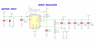
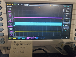
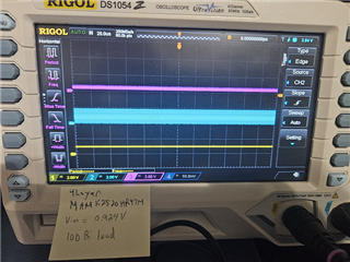
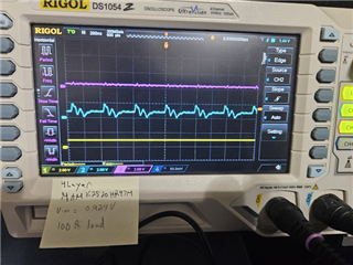
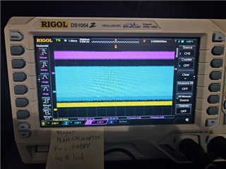
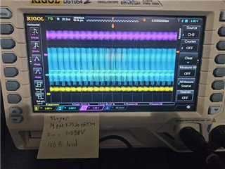
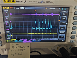
I am using the TPS61021A to boost a single AA up to 3.6V.  Current 3-15 mA the majority of the time.  However, it may go up to 120mA for a few seconds and up to 300mA for a few hundred milliseconds.  Web bench and Figure 3. in the datasheet imply that it should have no issue handling the 300mA continuously even just under 1V input.  However, in testing, with the circuit hooked up to a bench supply, even 35mA drags the output down to 3.2V when the input voltage goes below 1.4V (which is the high end of the AA battery).  The circuit won't even start with a 180mA load if the input is below 1.2V. 

I have tried different input and output capacitors and a variety of inductors that meet or exceed the specifications of the ones suggested by Web bench.  I've tried multiple capacitors in the 10-22uF, in addition to 100uF capacitors (both ceramic and electrolytic)

Some of the inductors I've tried have included:

AMDLH5030S-R47MT

MHE0503R33M-10

AIP0530GX-1R0MPBDG

MAMK2520HR47M

NRS5030TR47NMGJ

I've tried multiple caps like:

C2012X7S1A226M125AC

LMK325BJ106MD-T

LMK325ABJ107MM-P

LMK212BBJ226MD-T

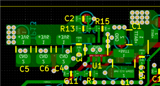
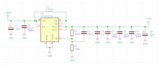
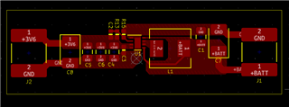
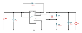
Schematic is per the Web bench design; layout is tight with components close and continuous copper pours.

Is this still the best part for boosting a single cell application up to 3.6V with loads up to 300mA?

  • Hi Kris,

    The expert is out of office today, and he will feedback you asap. Please take patience. 

  • Hello Kris,

    Did you check the input voltage while you drew current? Batteries can have a very high internal impedance which would reduce the input voltage at the battery and device if the current increases.

    Best regards,
    Brigitte

  • Brigitte,

    Yes, I had four multimeters plus the readout on the power supply I was using (BK Precision 1627A).  I read both the input and output voltages, in addition to the currents.  I read the input voltage at the board as the multimeter caused a drop for it's reading as did the test wires (18 AWG).  When I brought the input voltage down very low with a large load, I removed the multimeter on the input side and used the current reading on the power supply (it was near identical to the Fluke 87 V I was using).

    I spun some new test boards with a layout identical to the datasheet and compared two board that used one C2012X7S1A226M125AC on the input, two on the output and   MHE0503R33M-10 (330nH, 19.2A, 3.6mOhm) and AIP0530GX-1R0MPBDG (1uH, 10.5A, 8.5mOhm) inductors.  The 1uH inductor performed reasonably well in this test.  I went up to a ~171mA load and only saw an output voltage drop when I went down from 1V to 0.9V.  It was able to start-up with that load as well, even at 0.9V.  The board with the 330nH inductor would not start up until the input voltage was raised over 1.8V.

  • Hi Brigitte ,

    Appreciate your help about this case.

    Hi Kris,

    Thanks for the detailed information. Travis will help to answer the question when he is back.

    Hi Travis,

    Could you help on this case?

  • Thanks Brigitte and nini for supporting this case.

    Hi Kris,

    • Schematic is per the Web bench design.

    There are a lot of webench design based on TPS61021A. Please share the schematic and layout directly.

    • However, in testing, with the circuit hooked up to a bench supply, even 35mA drags the output down to 3.2V when the input voltage goes below 1.4V 

    I would like you to capture the waveform of Vin, SW Pin, Vout. Place the waveforms in the same screen. Capture one waveform of 1ms/div time scale and another waveform of 20us/div.

    Best Regards,

    Travis

  • I will capture the waveforms and post them.  Here is the original application board.  It is a 4 layer board with the +vbatt coming in on the power layer (not shown) and was designed with the MAMK2520HR47M as the inductor.  The 10uF are CL21A106KOFNNNE. 

    Part were swapped out for the ones listed above, however the larger inductors did not fit well, so I created some simple l layer test boards that followed the layout in the datasheet exaclty.

    C7 and C8 were just in case I needed bulk capacitance from the test lines.  They are not populated, neither is C6.  C1, C3 and C4 were populated with  2012X7S1A226M125AC.  Two identical boards were created with different inductors only: MHE0503R33M-10 (330nH, 19.2A, 3.6mOhm) and AIP0530GX-1R0MPBDG (1uH, 10.5A, 8.5mOhm).

  • Got slightly different results with the oscilloscope vs. multimeters.  Some better, some worse.  It got slightly better when nothing was connected to SW.

    Would not start-up until the voltage got over 1V.

    The 100R load is ~35-36mA.  This board won't even start at 1.6V with a 17R load (~211mA).  The 1 layer test board with the MHE0503R33M-10 (330nH) will start at ~1.2V with the 100R load and will not start up with the 17R load.  The 1 layer test board with the AIP0530GX-1R0MPBDG (1uH) has not issues with the 100R load, but will only start up with the 17R load at around 1.5V.  This is worse performance than with the multimeter.  However, the multimeters reduced the load current from ~211mA to ~171mA, so that may be the reason.  When the circuit won't start, the traces looks like above at 0.924V.

    WEBENCH is giving me this when I input Vin = 0.9-0.9V, 3.6V Vout @ 0.250A:

    On the test boards, I'm using the recommended 22uF output caps (2012X7S1A226M125AC) for all three 22uF caps and inductors that exceed the specs of the one listed.  I used a 348K resistor vs. the 357K, but that should be easier to meet since it lowers Vout slightly. 

  • Hi Kris,

    Thank you for the waveform.

    About Start up:

    I'll check on bench to conmpare with your result.

    Best Regards,

    Travis

  • Hi Kris,

    Sorry for the late reply. I wasn't in the office last week. I've tested on my bench and 100ohm load is close to the IC maximum start up ability. The device current capability during start up phase depends on Vin. So we recommend reducing load during 0.9V start up or choose TPS61299. TPS61299 has less current capability after start up but the current capability during start up is stronger than TPS61021A.

    Best Regards,

    Travis

  • Travis,

    Interesting, that isn't a part that Web Bench suggests.  Looking at the datasheet, I'm wondering if the TPS612997 might be the best variant as limiting the current less would be better for a start-up with a higher load, I would think.

  • Hi Kris,

    The difference between TPS61299 and TPS612997 is the threshold of which current limit is triggered. This does not affect the early start up stage when your device cannot start up. But only affects the steady state when the IC already start up.

    Best Regards,

    Travis