This thread has been locked.

If you have a related question, please click the "Ask a related question" button in the top right corner. The newly created question will be automatically linked to this question.

UCC28730-Q1: How valley switch is realized in FM/AM mode

Part Number: UCC28730-Q1
Other Parts Discussed in Thread: UCC28730

Tool/software:

Hi expert,

UCC28730 has this curve for EA output to current output.

Between 1.3-2.2V, IPP control a fixed on-time and FM increase the switch frequency to increase the output current.

Between 2.2V-3.55V, frequency is fixed to 28kHz and IPP goes up to increase the on-time and increase the output current.

In this two mode, the on-time and switching period is fixed by control method, how does valley switch works? I think valley switch will directly turn on the mosfet and influence the control loop.
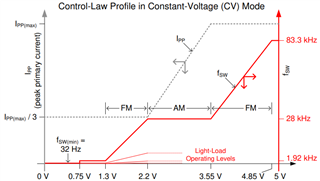
For the final 3.55-4.85V, 28730 is just work like 1.3-2.2V, so during the whole range, do we need to design it all in DCM mode? (even in the CC mode, 4.85-5V?)

Thanks!

  • Hi Jass,

    Thank you for reaching out.

    You are correct on your observations. The valley switch is internally done by monitoring the aux pin voltage (scaled down) and has a dv/dt kind of detection to find the minimum. There is also frequency clamp internal implemented where you will sometimes see this toggling between valleys, but the logic as such is same. 

    Yes, the logic works same in all modes, only difference will be in the number of valleys depending on the load condition.

    Regards,

    Harish