


Tool/software:
Hello , I would like to know the following
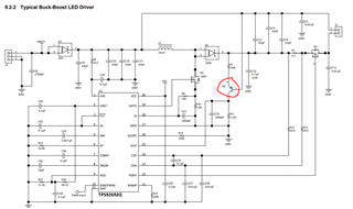
1.) what is the function of Q2 PNP transistor in the application circuit shown in datasheet? how to select it?
2.) How is boost to battery and Buck boost topology different? Is there an excel sheet available to calculate for boost to battery?
3.)Cout value obtained in "buck boost " excel design calculation sheet is connected between LED+ and GND or LED+ and LED- ?
