This thread has been locked.

If you have a related question, please click the "Ask a related question" button in the top right corner. The newly created question will be automatically linked to this question.

TPS53355: Question about TPS53355DQPT

Part Number: TPS53355

Tool/software:

Hello:

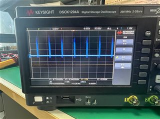
When using the TPS53355DQPT chip, it was found that there was no voltage output. The circuit was 12V-5V. The output waveform of the LL pin was abnormal. The picture is in the attachment. Please check it. Please also help locate the problem. The circuit diagram is also in the attachment. In addition, the chip itself is not hot, and there is no obvious short circuit in the back-stage measurement. Thank you!!!

    P5V0.pdf

  •  

    I am heading out for a week, so someone else from the team will pick this up while I am out, but from the switch-node waveforms, it looks like the switch-node voltage  is dropping rapidly as the part starts switching.

    1) Check to see if the input voltage at the IC (after L113) is dropping as the converter turns on.

    2) Check the output to make sure there is not a short or excessive load on it

    3) Check CE186 and CE187 to make sure they are not installed backwards (polymer capacitors are low impedance when connected in reverse) 

  • Hello Jimmy, 

    Very hard to see what is happening from the plots you provided 

    please find the calculator tool as attached and double check the design, most likely the inductor is not hight enough 

    sluraz7a (1).zip

    Thanks! 

    Tahar

  • What is load current you are testing this at? Also, in the schematic, CE186 and CE187 are present - they look like high ESR caps. Can you please confirm if those are installed? Those can interfere with stability of the device. Also, would like to see zoomed in waveforms of VIN, VOUT, SW and VFB if possible during startup and steady-state both to see what may be happening.

    Thanks,

    Amod

  • Hello Peter:

    1) Check to see if the input voltage at the IC (after L113) is dropping as the converter turns on.

    1. When the IC is turned on, the voltage drops.

    2) Check the output to make sure there is not a short or excessive load on it

    2. There is no short circuit or overload.

    3) Check CE186 and CE187 to make sure they are not installed backwards (polymer capacitors are low impedance when connected in reverse) 

    3. CE186 and CE187 are installed normally.

    Thanks!!!

  • Hello Tahar:

    This circuit is a mass production circuit, and the values ​​are fine,Thanks!!!

  • Hello Amod:

    I measured the waveforms of VIN, VOUT, SW and VFB and put them in the attachment. Please help analyze them.

    In addition, the 12V inside is the 12V input voltage after disconnecting L113.


    Looking forward to your reply! I hope you can help me analyze the reason

    Waveform Measurement.zip

  • Hi Jimmy,

    Did you have a zoomed in waveform during startup and zoomed out with startup+steady-state for all these signals at the same time? Can you also add VREG signal?

    It is not clear but it looks like VIN ramps up quite slowly taking >10ms and is very noisy with big dips all the way down to <5V at the early stages. If output current is spiking to high levels, there can be a dip on the input voltage. One way to confirm if there is a large output current or short circuit is to monitor the inductor current. Also large currents can cause such repeatable shutdowns and startups due to overcurrent protection mechanism of this IC. You can lift the inductor from the pad near the output caps and add a wire loop from the inductor to the pad and monitor this current.

    If VIN ramps too slowly, there is a possibility of UVP being triggered but it is not clear if VOUT ever reaches the desired 5V steady-state after startup. That is why the waveforms above of all signals together can help analyze and rule out some of the possible causes.

    Finally, is the issue following this specific IC or does this IC work fine on other boards? An A-B-A swap can help determine if the issue is specific to the IC or a board. How many boards/ICs are showing this issue?

    Thanks,
    Amod