Tool/software:
Hi team,
Blue is output voltage
Red is EN
Yellow is channel 1 output current
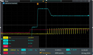
The customer's output current adjustment starts after the output voltage stabilizes. From the waveform, it can be seen that the current is adjusted to the maximum value by gradually increasing the duty cycle. From the graph, it feels like it is around 7-8 grids, and the adjustment time is about 320ms. Is this normal?
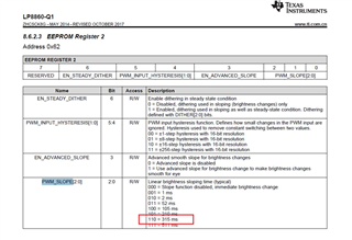
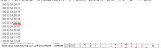
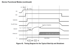
At first I thought the customer set the PWM SLOPE to 315ms. But the customer actually set it to 100 (105ms). Please help me figure out where the gradual increase in the PWM duty cycle is determined, and whether the time for the gradual 100% duty cycle is normal.