This thread has been locked.

If you have a related question, please click the "Ask a related question" button in the top right corner. The newly created question will be automatically linked to this question.

LM5149-Q1EVM-400: Questions about weird operation of LM5149-Q1EVM-400

Part Number: LM5149-Q1EVM-400

Tool/software:

To whom it may concern, 

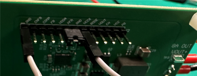
I ordered an evaluation board of LM5149-Q1EVM-400. When I powered up the evaluation board for the first time, there is no 12V output (I used the scope to measure the 12V output, and found that it is just a very short pulse). Then, I tied the PFM/SYNC to the ground and the module starts to output 12V. 

So my first question is that, to generate the stable 12V output, the PFM/SYNC must be tied to GND? and cannot be floating?

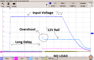
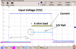
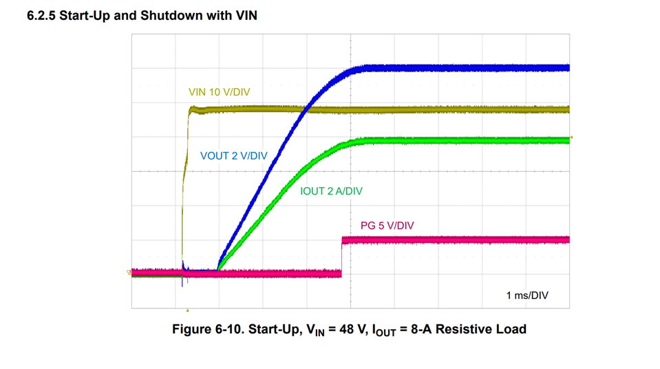
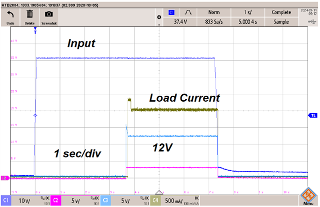
Another question is that, when I applied 72V at the input, the 12V output is generated after about 4 seconds and with a significant overshoot (The phenomenon is same with 48V input). I attached the photo below. The results are totally different from the startup tests results in the datasheet of LM5149-Q1EVM-400. So, why there is such long delay between input voltage and output voltage, and why there is such a significant overshoot on 12V rail.

Thanks.

Regards,

Eric

  • Hello Eric,

    The PFM/SYNC pin is an active pin that will need a clock signal or be correctly terminated.  Are the waveforms you have provided with the PFM pin grounded.  this should not happen under normal use operation.

    below are the waveforms you should expect to see on the EVM.  this is for 48V in.

    Hope this helps.

    David.

  • Hi David,

    Many thanks for your reply. 

    What I did on the evaluation board is only to tie VCCX to GND and PFM to GND. Then, when I applied 48V input voltage, after about 4 seconds, the 12V voltage output shows up and with a significant overshoot. Should I assume that the evaluation board that I purchased from Digikey is damaged one?

    Thanks.

    Regards,

    Eric

  • Hello Eric,

    I am not certain what has damaged the board, it could be that leaving the pin floating did something?  difficult for me to say for sure, however leaving the pin floating means the device was waiting for a clock signal, or it was trying to determine if it's to work in FPWM, or PFM mode.

    is the white wire to VCCX in the photo a jumper?  Or is it a voltage to VCCX?

    David.

  • Hi David,

    As I said in previous email, the VCCX and PFM are tied to GND all the time and never been left floating. (I tested PFM pin floating or tied to VDDA, and it didn't generate 12V output at all).

    The VCCX pin is tied to GND pin by using the white wire jumper. And, the PFM pin is tied to GND through the black jumper. 

    If you think my configuration is correct and the long delay and overshoot are not as expected, I will buy another evaluation board and try again, although I don't want to spend more money on this prototype.

    Thanks.

    Regards,

    Eric

  • Hello Eric,

    Please go ahead and order another EVM, please retest, please let me know if you continue to see issues.

    I will also check this next week in anticipation of you experiencing another issue.

    Thanks,

    David.