Other Parts Discussed in Thread: BQ25180, , USB2ANY, BQ25180EVM, TI-CHARGER-GUI
Tool/software:
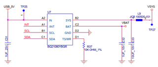
UUSB_5V = 0 (No USB cable inserted)
Step1. Switch on
Step2. VBAT (4.0~4.1V) input to BQ21080YBGR
Step3. VSYS has no output
This thread has been locked.
If you have a related question, please click the "Ask a related question" button in the top right corner. The newly created question will be automatically linked to this question.
Tool/software:

UUSB_5V = 0 (No USB cable inserted)
Step1. Switch on
Step2. VBAT (4.0~4.1V) input to BQ21080YBGR
Step3. VSYS has no output
Hello,
Could you please provide waveform captures for both a normal startup and a startup when the VSYS issue occurs?
Additionally, could you include the register dumps during each of these scenarios?
Best regards,
Alec Lehman
Hi Alec,
Please refer below setting.
BQ25180_write(BQ25180_ICHG_CTRL,0xb4); // battery charging disable, ICHG is 250mA
BQ25180_write(BQ25180_VBAT_CTRL,0x55); // set VBAT is 4350mV
BQ25180_write(BQ25180_TMR_ILIM,0x4F); // set input current limit is 1100mA
BQ25180_write(BQ25180_IC_CTRL, 0x87); // disable watch dog
BQ25180_write(BQ25180_SYS_REG,0x20); // sys regulation voltage is 4.4V, v1008 not imprement
BQ25180_write(BQ25180_ICHG_CTRL,0x34); // enable, set ICHG is 250mA
BQ25180_write(BQ25180_SHIP_RST, 0x01); //disable shipping mode
Hello,
Thank you for providing the waveforms and register settings.
Could you please provide the status registers when this issue occurs? It would be most helpful to see all of the register values, but I would at least like to see STAT0, STAT1, FLAG0, and CHARGECTRL1.
It's possible that there is a battery overcurrent event happening when the battery is being inserted.
Could you provide a waveform of a VIN insertion in an instance where VSYS does not come up, if you're able to recreate the issue? I would expect to see VSYS come up when VIN is inserted.
Best regards,
Alec Lehman
Hi Alec,
1. What tools can be used to read register values?
2. If there is no output on Vsys, the voltage will appear on Vsys when a USB is inserted
3. The defect probability is approximately 1/60
4. When the switch is off, there is no voltage on BAT Pin
When the switch is turned on, VBAT will have voltage input to MCU C2

Hello,
1. What tools can be used to read register values?
You will need to read the registers through your host MCU. Please refer to section 8.5 of the BQ21080 datasheet for the device registers.
2. If there is no output on Vsys, the voltage will appear on Vsys when a USB is inserted
Thank you for confirming that VSYS comes up when VIN is inserted.
4. When the switch is off, there is no voltage on BAT Pin
When the switch is turned on, VBAT will have voltage input to MCU C2
Could you please clarify what you mean by MCU C2?
Best regards,
Alec Lehman
1. What tools can be used to read register values?
You will need to read the registers through your host MCU. Please refer to section 8.5 of the BQ21080 datasheet for the device registers.
[Hemry] Do I need to use an external tool
2. If there is no output on Vsys, the voltage will appear on Vsys when a USB is inserted
Thank you for confirming that VSYS comes up when VIN is inserted.
[Hemry] Yes
4. When the switch is off, there is no voltage on BAT Pin
When the switch is turned on, VBAT will have voltage input to MCU C2
Could you please clarify what you mean by MCU C2?
[Hemry] BQ21080,C2 Pin
Hello Hemry,
[Hemry] Do I need to use an external tool
We have the TI Charger GUI which is designed to work with a USB2ANY and can be used to communicate with the charger through I2C. We typically use TI Charger GUI and a USB2ANY with our evaluation modules (EVMs), but it will work if you are able to wire your SDA and SCL pins to it.
2. If there is no output on Vsys, the voltage will appear on Vsys when a USB is inserted
Thank you for confirming that VSYS comes up when VIN is inserted.
[Hemry] Yes
This could indicate that the device is entering a BATOCP event lockout, as this lockout can only be exited by inserting VIN. Could you please provide a waveform of VBAT, VSYS, and IBAT during a startup sequence where SYS does not come up? It would be helpful to see if IBAT is going above the BATOCP threshold.
Best regards,
Alec Lehman

1. Right picture is VBAT/VSYS waveform
2.What is the maximum specification that IBAT
Hello Hemry,
2.What is the maximum specification that IBAT
The IBAT overcurrent protection can be set to 500mA, 1000mA, 1500mA, or it can be disabled. Please refer to section 8.5.1.7 of the BQ21080 datasheet. IBAT_OCP can be configured in the CHARGECTRL1 register, REG0x06.
Could you please confirm what IBAT_OCP is set to? Additionally, a waveform of IBAT would be helpful if you have a current probe to measure it. Otherwise, could you please provide what your expected system load is?
Best regards,
Alec Lehman

1.IBAT_OCP setting default value is 1000mA
2.Power on max current is 130mA (400us), Average current is 11mA
I think it should be lower than the OCP setting.
Hello Hemry,
Thank you for providing that waveform of your load.
I'd like to take a moment to align on the issue to ensure I understand it correctly:
I'd also like to attempt to recreate this issue and have a few questions for further investigation:
Best regards,
Alec Lehman
1. Test condition: Power on for 5 seconds (mouse working) => Power off for 5 seconds => Power on for 5 seconds, and so on.
2. Defect probability: 1/60 cycles (the same sample).
3. Pulsing current: This is the IBAT, as shown in the waveform (29 seconds).

Hello Hemry,
I have done some testing and am able to recreate this issue. This issue seems to be related to BAT starting up into a significant system load. Please see the below waveform of a capture where SYS does not come up. In this instance, I hot plugged BAT into a 1A system load. However, I have also seen this issue happen when starting into a 200mA system load. It seems that this issue is more likely to happen the sooner that I plug in the battery after disconnecting it from the device.
SYS fails to rise on startup:
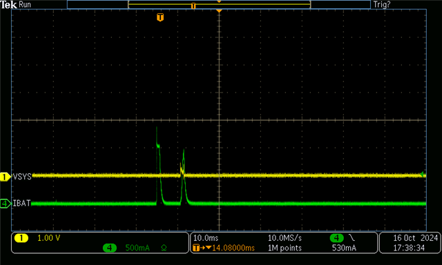
I will keep investigating this issue, but in the meantime, could you share more details about your system load? Generally, the more capacitance on SYS, the more inrush current there will be to SYS from BAT. It would be helpful to know how much capacitance is on your SYS.
Best regards,
Alec Lehman
Do you have any recommendations for the capacitor on SYS?
1. Chager[BQ21080YBGR] : 10uF
2. Boost : 4.7uF
3. Buck : 10uF+0.1uF
Hello Hemry,
Thank you for providing the capacitors on SYS. That amount of capacitance seems fine, so it's possible the issue is related to the amount of current the downstream components on SYS are drawing in some startup cases.
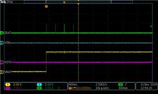
I did more testing on this issue. Here is a waveform of a BATOCP event happening on a device startup from battery:
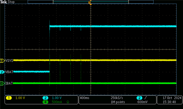
VBAT = 4V, ISYS = 900mA
Please note the horizontal scale of this waveform, 400ms, is wider than the issue waveform that you provided, 2ms. It's possible that these pulses, which indicate a BATOCP event, were missed in your waveform capture.
Could you please try the following:
It would be helpful to confirm whether or not this issue is related to your specific system load and not the IC.
Best regards,
Alec Lehman
Hello Hemry,
I just wanted to reach out to see if you've performed any tests with the SYS load disconnected.
Please let me know, and we can continue from there.
Best regards,
Alec Lehman
Hi Alec,
Vsys has no output , so the backend load shouldn't matter, right?
Moreover, the backend load is 5~11mA*3.8V
When power-on, the battery peak current (IBAT) is 130mA/3.8V/400µS, average current of 11mA/3.8V. ( refer below picture )
This issue continues to occur in current production. Out of 520 units produced, 35 units have no Vsys output after powering on, but they work normally once a USB cable is inserted.
We have not yet identified the issue. Do we need to provide samples for your analysis?

Hello Hemry,
Vsys has no output , so the backend load shouldn't matter, right?
If the BATOCP threshold is reached, then the BATFET will turn off. The device will turn on the BATFET 250ms after being turned off by the initial BATOCP condition to check if BATOCP is triggered again. If the BATOCP condition is triggered 4 to 7 consecutive times within 2s, the BATFET will remain off until a valid VIN is connected. Therefore, it is possible that the device is entering BATOCP on a battery startup. I understand that your expected max system load is around 130mA, but there could still be an IBAT spike caused by capacitance on SYS.
Given that SYS comes up when an adapter is inserted, it strongly suggests that this issue is related to the BATFET turning off as a result of a triggered protection, such as BATOCP.
Right now, I would like to see the register dumps before moving forward with receiving your hardware.
If we can confirm that this issue is related to BATOCP or some other device protection, then we can investigate further.
Best regards,
Alec Lehman
Is the default BATOCP threshold set to 1000 mA?
I’ll check the other information and get back to you.
Hi Alec ,
I have received the USB2ANY and BQ25180EVM Kit, but I’m unable to connect. Could you advise on what might be causing the issue?

Hello Hemry,
Is the default BATOCP threshold set to 1000 mA?
Yes, the default BATOCP is set to 1000mA in REG0x06 (bits 7-6). Please refer to section 8.1.5.7 of the BQ21080 datasheet for more details.
I have received the USB2ANY and BQ25180EVM Kit, but I’m unable to connect. Could you advise on what might be causing the issue?
You may need to update the firmware on the USB2ANY to version 2.9.0.3. Please follow the steps outlined in the answer provided in this E2E thread: BQ25792EVM: USB2ANY to connect to his BQ25792EV
Best regards,
Alec Lehman
Hello Hemry,
There are some other threads with similar questions, were they able to help resolve the USB2ANY issue?
For example, here is one: https://e2e.ti.com/support/amplifiers-group/amplifiers/f/amplifiers-forum/1404257/usb2any-usb2any-device-fails-update-memory-verification-error
Sincerely,
Wyatt Keller
This issue is due to incompatibility with Win11, but my system is Win10. Is there any command that could help?"

--------------------------------------------------------------------------------------------------------------------------------
This is the waveform of the TS/MR pin.
The TS/MR pin voltage on the failed sample is 0. Could it be entering shipping mode?

Hello Hemry,
Yes, it is possible that the device is entering ship mode. Ship mode can be entered via I2C or a long button press, although there is no push button in your schematic. However, if the TS/MR pin is somehow being held low for a duration longer than tLPRESS (default 10s, configurable in Reg0x08<bits 7-6>), the device will enter ship mode. If an adapter is present when ship mode is requested, the device will enter ship mode upon the adapter being removed.
Could you please check if the TS/MR pin is unintentionally being shorted?
I see that you tried updating the USB2ANY firmware to version 2.8.2.0, which didn't work. Could you please try updating to version 2.9.0.3? The txt file is available in this thread: BQ25792EVM: USB2ANY to connect to his BQ25792EVM
Please let me know if that works. I've seen the memory verification error before, but I was able to get it to work after unplugging and plugging the device into my computer.
Best regards,
Alec Lehman
Hi Alec ,
USB2ANY_2_9_0_3.txt has been selected for flashing But the flashing still failed.
Do you have any other suggestions? Or.. could you provide an updated USB2ANY tool?

Hello Hemry,
Are you using the firmware loader from the SDK mentioned in this thread?
BQ25792EVM: USB2ANY to connect to his BQ25792EVM
This thread could be helpful too:
USB2ANY: USB2ANY fails to update
I've seen this issue before, but the firmware usually updates after a few tries. I recommend closing and reopening the firmware loader before trying again.
Please let me know if you still have issues updating the firmware.
Best regards,
Alec Lehman
Hello Hemry,
I recommend creating a new thread with 'USB2ANY' as the part number to resolve that issue.
It seems that either (1) ship mode or (2) BATOCP is the reason why SYS is not rising on startup. This is consistent with the behavior that SYS rises when an adapter is inserted.
Best regards,
Alec Lehman
Hi Alec ,
1. The USB2ANY update has been completed and it can now connect to the chip (BQ21080).
2. S/MR pin is not connected to GND ,
3. It may not have entered shipping mode; it looks more like a crash.
If it enters shipping mode, internal data should be read, but it seems there is no data being read.
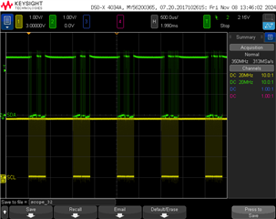
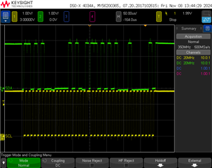
NG Status : Only one signal was sent, and then there was no signal

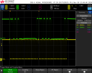
Normal Working Status : below 3 pictures
Hello Hemry,
I am glad to hear you were able to update the USB2ANY. Can you hardwire it to your boards experiencing the SYS issue? Table 2 in the USB2ANY User's Guide provides the cable pinout: on the USB2ANY connector, pin 9 is SCL, pin 10 is SDA, and pin 6 is GND.
USB2ANY User's Guide: USB2ANY Interface Adapter
Alternatively, try connecting your SYS load to the BQ25180 EVM to observe the SYS behavior and read the registers from the EVM:

Please let me know what you find.
Best regards,
Alec Lehman
Hi Alec ,
1. NG Status (left picture) : I2C only one signal was sent, and then there was no signal.
So can't link "TI-CHARGER-GUI", and registers can't be read."
Device flags are untriggered, it looks more like a crash
2.Normal Working Status (right picture)

Hello Hemry,
1. NG Status (left picture) : I2C only one signal was sent, and then there was no signal.
It seems that the device is off in this case. That I2C signal is most likely the USB2ANY trying to connect to the device but not receiving an acknowledge (ACK).
2.Normal Working Status (right picture)
Since the ILIM and VDPPM flags were triggered, an adapter was likely present in this instance, meaning the device could communicate while being powered by VIN.
Best regards,
Alec Lehman
Hi Alec,
1.Are you reading the registers of the device on your board or the EVM?
[Hemry] Yes,If the device has not failed, the registers should be readable.
2.If you're able to recreate this issue on the EVM, could you please provide a waveform of VBAT and VSYS during the failure, using the test points on the EVM?
[Hemry] Why replicate it on the EVM when the issue can be reproduced on the device mouse?
3.Please provide the registers of the non-working device after connecting an adapter to it. Seeing all of the register values would be very helpful, especially the device status and flag registers.
Earlier in this thread, you provided waveform captures of the failure, showing VBAT, VSYS, and SDA. From your schematic, I see that you have test points on the IN and SYS pins. However, I do not see a test point on the BAT pin. When you captured these waveforms, where were you measuring VBAT?
[Hemry] VBAT=4.2V [BQ21080 ,Pin-C2]
4.Is there a battery protector IC on your battery pack? This could be disconnecting your battery from the device. Given that you're able to recreate this issue on the EVM, it seems the battery pack is the one component common to both your board and the EVM.
[Hemry] No battery protector IC , Only the battery switching circuit.
Hello Hemry,
[Hemry] Yes,If the device has not failed, the registers should be readable.
The registers can be read as long as either VBUS is present and above VIN_UVLOZ, or VBAT is present and above VBUVLO. Since you were unable to read the registers, it seems the device may not have been connected to the battery pack, which could be the root cause of the issue.
2.If you're able to recreate this issue on the EVM, could you please provide a waveform of VBAT and VSYS during the failure, using the test points on the EVM?
[Hemry] Why replicate it on the EVM when the issue can be reproduced on the device mouse?
It's important to know whether you were able to recreate this issue on the EVM with your battery pack. This would tell us whether the issue is specific to your board. Please clarify what board you were testing on when you were not able to read the device registers through the TI Charger GUI.
[Hemry] No battery protector IC , Only the battery switching circuit.
In the setup picture you previously provided, it appears you're using a battery pack that typically includes a protector circuit. Could you please provide the part number of the battery pack?
Best regards,
Alec Lehman
[Hemry] VBAT=4.2V [BQ21080 ,Pin-C2]
What did you measure VBAT to be when you couldn't communicate with the device? I'd like to know whether the voltage reached the BAT pin on the device from the battery pack.
Best regards,
Alec Lehman
Hello Hemry,
Thank you for confirming. I had sent two replies -- could you take a look at the first one too and let me know your responses?
Best regards,
Alec Lehman
Hi Alec,
[Hemry] Yes,If the device has not failed, the registers should be readable.
The registers can be read as long as either VBUS is present and above VIN_UVLOZ, or VBAT is present and above VBUVLO. Since you were unable to read the registers, it seems the device may not have been connected to the battery pack, which could be the root cause of the issue.
[Hemry]
1.The BUVLO default is 3.0V, but the battery voltage is 4.2V, so this is likely not the cause."
2.If the battery voltage falls below 3.0V, will it cause Vsys to have no output? Can this be resolved if the battery voltage rises above 3.0V?"
2.If you're able to recreate this issue on the EVM, could you please provide a waveform of VBAT and VSYS during the failure, using the test points on the EVM?
[Hemry] Why replicate it on the EVM when the issue can be reproduced on the device mouse?
It's important to know whether you were able to recreate this issue on the EVM with your battery pack. This would tell us whether the issue is specific to your board.
[Hemry]
The BQ21080 is used in the mouse device. This issue does not occur in every unit and has a low reproduction rate. In your assessment, could it still be a battery pack issue?"
Please clarify what board you were testing on when you were not able to read the device registers through the TI Charger GUI.
[Hemry] Tested with PCBA
[Hemry] No battery protector IC , Only the battery switching circuit.
In the setup picture you previously provided, it appears you're using a battery pack that typically includes a protector circuit. Could you please provide the part number of the battery pack?
[Hemry] Please refer to the attachment
Hello Hemry,
I appreciate your responses.
1.The BUVLO default is 3.0V, but the battery voltage is 4.2V, so this is likely not the cause."
2.If the battery voltage falls below 3.0V, will it cause Vsys to have no output? Can this be resolved if the battery voltage rises above 3.0V?"
Understood that the battery voltage is 4.2V. Since you were unable to communicate with the device, my concern here was that the battery pack had somehow been disconnected from the device, possibly as a result of the battery protection circuit opening and disconnecting the battery from the BQ21080.
Yes, if the battery falls below BUVLO, then the BATFET will turn off, disconnecting the BAT to SYS path.
The BQ21080 is used in the mouse device. This issue does not occur in every unit and has a low reproduction rate. In your assessment, could it still be a battery pack issue?"
It's possible that the battery protection circuit is causing this behavior.
[Hemry] Tested with PCBA
Thank you for confirming.
You have provided a lot of information in this thread, and I really appreciate it. Now that you are able to read the device registers, it would be most helpful if you could recreate the issue on your mouse PCB and provide the following:
A screenshot of all the device register values will work fine. With all of this information, we can best move forward.
Best regards,
Alec Lehman
Hi Alec,
1.The battery pack is not disconnected from the device, as there is voltage detected at Pin C2 of the IC 'BQ21080
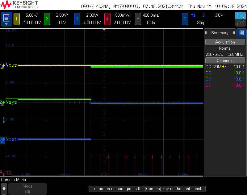
2.Measure the following four signals, correct?

Hello Hemry,
Yes, those are the four signals I'd like to see. I understand it might be difficult to recreate the problem, but this information would be very helpful.
Best regards,
Alec Lehman
Hi Alec,
1.The battery pack is not disconnected from the device, as there is voltage detected at Pin C2 of the IC 'BQ21080
2.Measure the following four signals, correct?

3.EN_PUSH default is Enable,
Does changing it to disable mean that the button will have no functionality? What side effects might occur ?

Hello Hemry,
3.EN_PUSH default is Enable,
Does changing it to disable mean that the button will have no functionality? What side effects might occur ?
If the push button is disabled, the device will not pulse the TS/MR current source to check if a button is pressed.
It might be worth checking if the device is unintentionally entering shutdown mode. It's possible that firmware could be unintentionally causing this. In shutdown mode, the TS/MR current source will not pulse, and the device will not communicate over I2C. However, it can wake from this mode if a valid adapter is inserted.
Best regards,
Alec Lehman
Hi Alec,
1. Still waiting for your reply.
=> Measure the following four signals, correct?

2. Layout

Hello Hemry,
1. Yes, please measure those four signals.
2. I do not see any apparent issues with the layout. However, I would recommend covering the GND pads of the passive components with the GND pour.
Best regards,
Alec Lehman
1. I will provide the measurement data later.
2. Covering the GND pads may cause the IC to float during SMT, Is this still recommended?
Hello Hemry,
1. I will provide the measurement data later.
Thank you, this data will be very helpful.
2. Covering the GND pads may cause the IC to float during SMT, Is this still recommended?
It's generally preferred to connect the GND pads of resistors and capacitors directly to the GND pour, although this doesn't seem related to the SYS startup issue.
Best regards,
Alec Lehman
Hi Alec,
1. Pls review below waveform
Fail waveform :
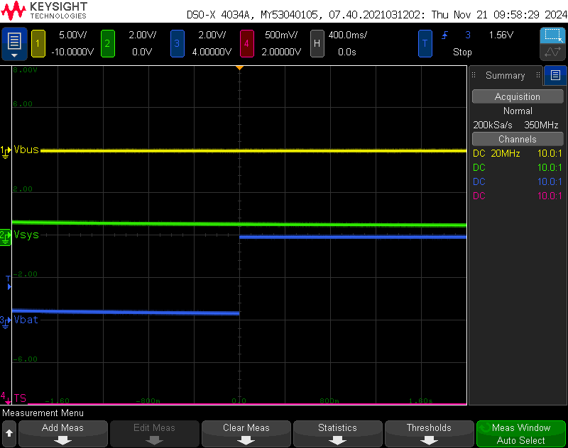
Pass waveform :
2. The GND pad has been connected via the bottom layer.
