


Tool/software:
Hello expert,
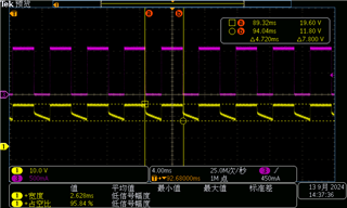
I am testing TPS92520, the waveform of output voltage and output current. Why is the waveform of current PWM waveform and the waveform of voltage not PWM waveform? What is going on?
Tool/software:
Hello expert,
I am testing TPS92520, the waveform of output voltage and output current. Why is the waveform of current PWM waveform and the waveform of voltage not PWM waveform? What is going on?
