This thread has been locked.

If you have a related question, please click the "Ask a related question" button in the top right corner. The newly created question will be automatically linked to this question.

BQ40Z50-R2: Internal cell balancing problem with constantly changing discharge currents

Part Number: BQ40Z50-R2
Other Parts Discussed in Thread: BQSTUDIO, BQPRODUCTION

Tool/software:

Hi,

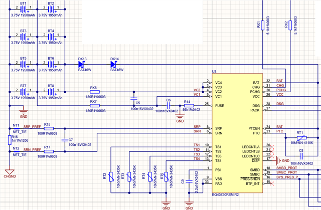
We have some 2S battery packs with BQ40Z50-R2 v2.08 that works fine. But there are some where there is serious imbalance (0.4V) between the cells. The circuit is similar to the EVM circuit.
To be free of previous error, I started a new config file (with firmware 2.08). The chemistry is set, the learning cycle was done, and the RA tables got updated. The cell balancing is enabled during rest and sleep too.

The packs are in rest now since two days, with CB is on. Cell 1 is at 3863mV, Cell 2 is at 4291mV.
But in BQ Studio, I see that "Cell 1 Current" and "Cell 2 Current" values are constantly shifting between 0 and -20mA. The imbalance between the cells remained the same after two days of balancing.


In this situation, cell 1 should not be discharged at all by the internal mosfet, right?
The config file is attached.

cb_current_problem.gg.csv

  • Hello,

    What is the value of the sense resistor being used in the circuit currently? If possible, can you please send a bqStudio log file depicting the situation above so we can take a deeper look?

    Regards,

    Anthony

  • Hello!


    A quick log file is attached, both cell currents jumps back and forth.The sense resistor is 1mOhm.

    CB_log.zip

    Because of some special requirements we are using 180oHm series resistors and two schottkey diodes. But those components should not really affect the cell balancing much except the maximum discharge current I think.

  • Hi Kovacs,

    Thank you for the log file, we will begin looking it over. Can you please confirm if the 8 cells in the image above are the only cells in use, along with why the VC3 and VC4 pins are not in use? Can you please give more information about the cell orientation?

    Regards,

    Anthony

  • Hi Anthony,

    This is a 2S6P pack. The 4 remaining cell is in an other PCB that's not shown in the picture above. Sorry, I should mention them already. So the total charge per series cells are around 10700mAh.

    VC3 an VC4 is tied to VC2 according to 8.3.5.4 point of the datasheet.

  • Hi Kovacs,

    Understood, thank you for the clarification. In the log file, it seems like the right conditions are being met for cell balancing in relax to occur, however the full charge capacity seems very low for the design capacity in use. Can you please confirm if this pack has been aged over time?

    Regards,

    Anthony

  • Hi Anthony,

    I think so, this pack came back from the customer. On the other hand, it went through relatively few cycles at the receiver, its use was more characterized by charging it, draining it, then charging it again...

    At the same time, I have a similar battery pack that has not yet been to a customer, but it has the same problem of different cell voltage. We do not know what causes this condition, during production only cells with nearly the same charge can be soldered into the pack.

    For reference, I also have a 3rd pack with me, which has already passed a few cycles, but there is absolutely no difference in cell voltage. That pack works fine with the same config.

    BattLogs.zip

    I uploaded a new log zip of today's status.
    Bat0 is the pack I posted the log before.
    Bat1 is the pack that has not visited the customer but has the cell voltage problem.
    Bat2 is the pack that works perfectly, even though it is used.

  • Hi Kovacs,

    Thank you for the files. Regarding the Bat2 and Bat1 files, is there any difference between what has occurred prior to the log files? After programming, has a Qmax update occurred in each of these devices?

    Regards,

    Anthony

  • Hi Anthony,

    Yes, Qmax values got updated after programming, when I did the deplete-recharge cycle.

    But today I re-checked the cell voltage values from the week and I see both Bat1 and Bat2 shows shows less voltage difference between the cells!
    Bat 1 went down from 428mV to 321mV difference, and Bat2 went down from 191mV to  159mV difference in about 5 days. With the limitations of internal balancing, this sounds realistic.

    But I still don't know why the Cell current values are "jumping" while CB is ON. Or maybe that "jumoing" is just an issue with displayed values and the balancing works fine?

  • Hi Kovacs,

    Thank you for the clarification.

    But today I re-checked the cell voltage values from the week and I see both Bat1 and Bat2 shows shows less voltage difference between the cells!
    Bat 1 went down from 428mV to 321mV difference, and Bat2 went down from 191mV to  159mV difference in about 5 days. With the limitations of internal balancing, this sounds realistic.

    Regarding this, is it possible to share the Balancing Time per mAh in each of the .gg file for Bat1 and Bat2? There is a possibility that these values are being calculated to large values, hence why it seems like it is taking a lot of time to reach a balanced state.

    But I still don't know why the Cell current values are "jumping" while CB is ON. Or maybe that "jumoing" is just an issue with displayed values and the balancing works fine?

    For clarification, has current calibration been completed for this board?

    Regards,

    Anthony

  • Hi Anthony,

    So far these packs used the default values for Bal Time/mAh Cell values:
    Cell1: 367, Cell2: 514

    Now I did the calculations, and these values should be 364 and 563. This may not cause much difference, but I update them.


    So far the current was not calibrated. The CC Gain values was at the default 1.036, now after calibration I see values around 1.008, so they was not too far off. I also updated these values today.

    I don't know what to do with CC_Offset calibration, afaik sluuav7c that should be done in BQProduction program, but that's not working because of some lengthy Java error message... - if CC_Offset calibration is even needed at all, it's unclear.

  • Hi Kovacs,

    Now I did the calculations, and these values should be 364 and 563. This may not cause much difference, but I update them.

    If possible, can you please try reducing the Relax Balance Interval Timer to force the gauge to update the Balancing Time parameters? Since these are at default, I would like to see if having them update is able to help the situation.


    So far the current was not calibrated. The CC Gain values was at the default 1.036, now after calibration I see values around 1.008, so they was not too far off. I also updated these values today.

    Was updating the current able to assist in the cell current values being seen?

    Regards,

    Anthony

  • Hi Anthony,

    I realized today, the jumping cell current values caused by the presence of the charger circuit that's part of the connector for the pack. It seems like the circuit tries to do something if there is voltage on it's output... I should have realized this sooner.
    So I think reducing "Relax Balance Interval Timer" is no longer needed.

    Thank you for your help!

  • Hi Kovacs,

    Understood, we are glad the issue has been solved! Please let us know if there are any other questions.

    Regards,

    Anthony