This thread has been locked.

If you have a related question, please click the "Ask a related question" button in the top right corner. The newly created question will be automatically linked to this question.

BQ77915: DSG FET always off

Part Number: BQ77915

Tool/software:

Hi all, 

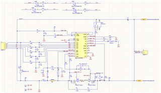
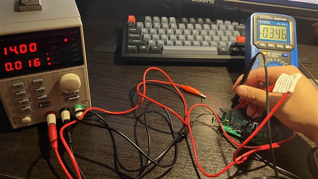
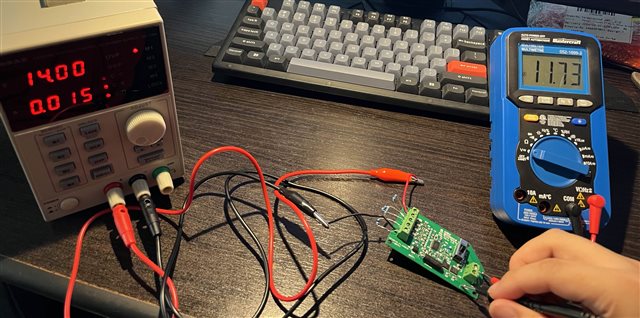
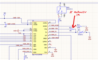
I am an engineering student and recently designed my first 4S BMS PCB using the BQ7791502 IC, based on the BQ77915 EVM design. When testing the PCB similarly to the EVM—by connecting a power supply to the battery terminals and using a 10K resistor as a load—I encountered an issue where the DSG FET continuously shuts off, despite the cell voltage sense inputs (VC1-5) showing around 4.0V, which is above the undervoltage threshold of 2.9V. Additionally, I noticed that the CHG FET does not turn off even when I turn up the supply voltage such that the cell voltages rise above the overvoltage threshold.

I'm not sure what's causing these problems and would appreciate any guidance or troubleshooting steps to help diagnose what might be wrong with my PCB. I've attached my schematic to this question and I am willing to attach my .PcbDoc file if it will help. (This is also my first thread on this site, so any pointers for future questions would also be appreciated!) 


  • Hi Felix,

    Did you measure the cell voltages at the device pins? I'm not too sure about the LEDs on the cells, they could be affecting accuracy.

    Regards,

    Max Verboncoeur

  • Hi Max, 

    Thanks for replying, I measured the voltage of the battery connectors (e.g. probed 1 and 2 of connector J1) as well as the voltage across the capacitors C3-C6 as they would be parallel to the batteries. Setting my DC power supply to 14V and 1A, the voltage of each cell would be ~3.5V, which is what I observe when probing the connectors. I've attached an image of my testing setup. Also the LEDs were included in the EVM schematic, and are supposed to indicate that cell balancing is occurring. 

    I fear it may be a layout issue but I'm not sure what to check. 

    Best, 

    Felix

  • Hello Felix,

    Another engineer will get back to you tomorrow regarding your issue. Thank you for your patience.

    Best Regards,
    Alexis

  • Hi Alexis, 

    Please let me know if there is any other information the team needs to help resolve my issue. 

    Thanks, 

    Felix

  • Hi Felix,

    Is there a load attached? What is the voltage at PACK-?

    Regards,

    Max Verboncoeur

  • Hi Max, 

    I'm currently testing with a 10K resistor load connected to PACK+ and PACK-. I've attached a video to better show what I'm seeing. When measuring the voltage across PACK+ and PACK- I first see approximately the source voltage for a few seconds (~14V in this case), but then the output voltage drops to 120mV which is when I assume the DSG FET turns off. 

    /cfs-file/__key/communityserver-discussions-components-files/196/IMG_5F00_0736.mov

    Thanks, 

    Felix

  • Hi Felix,

    If you power on the device without a load attached, does this behavior occur?

    Regards,

    Max Verboncoeur

  • Hi Max, 

    When powering on the device without any load, I observe a decreased output voltage, but not to the extent as with the load attached. I observe ~12V when probing the PACK+ and PACK- test points without a load attached. 

    Best, 

    Felix

  • Hi Felix,

    Are the FETs both on without the load attached? Ideally the PACK voltage is the same as the BAT voltage when the FETs are both on. Something has to be dropping that voltage.

    Regards,

    Max Verboncoeur

  • Hi Max, 

    I am actually just now taking a closer look at both MOSFETs and I am honestly a little confused by what I am seeing. 

    With a load:

    DSG FET: I can observe that the voltage between the drain and source is approximately equal to the source voltage (14V), which implies to me that it is not conducting and therefore off.

    CHG FET: I can observe that the voltage between the drain and the source is 0V, which implies to me that the FET is conducting and therefore on.

    Without a load:

    The voltage across the drain and source for both DSG and CHG FETs are 0V which implies to me that both FETs are conducting and therefore on. 

    However, when probing the CHG and DSG pins without a load (probing R8 and R9 with respect to ground), I observe that the voltage at these pins is 0V, which seems to contradict my previous assumption that the FETs were on. I also noticed that the PACK voltage without a load does not start at 11.73V, it actually drops to 11.73V from 14V after a few seconds of powering on the supply, similarly to the board's behavior under a load. I should also add that the voltage at these pins actually drop to from 12.60 V to 0 V with a similar timing to the PACK voltage dropping. 

    Additionally, I should also mention that when probing the CHG and DSG pins under a load (probing R8 and R9 with respect to ground), when the DSG pin voltage drops to 0V, the CHG pin's voltage actually drops to 0.6V too. This is right after powering on the supply with the DSG pin voltage dropping from 12.60V to 0V and the CHG pin voltage dropping from 12.60V to 0.6V. 

    I quite honestly have no idea how to interpret these results and whether or not the MOSFETs are on, my gut feeling tells me that the since the voltage at both DSG and CHG pins are dropping to near 0, that it might not necessarily be only be a false undervoltage fault. 

    I would really appreciate your insight. 

    Thanks, 

    Felix

  • Hi Felix,

    Without a load the PACK- node is floating, so the DS voltage of the FETs being 0V does not necessarily mean that they are conducting.

    Since both FET pins are turning off, I'm more inclined to think that there is a current fault triggering. I'm curious, if you start the pack with a load, wait for the FETs to turn off, then remove the load, does the device recover?

    Regards,

    Max Verboncoeur

  • Hi Max, 

    When removing the load while both FETs are off, the output voltage increases to ~12V. However, I believe that I found a lead. When ordering my PCB, I realized that R13 accidentally got swapped for a 1K resistor, whereas it was meant to be a 10K resistor, this would affect the voltage divider circuit with the thermistor and could accidentally set off an UTD or OTD fault. I've ordered some replacement resistors and will resolder those components. I will update you when I do. 

    Let me know what you think. 

    Best, 

    Felix

  • Hi Felix,

    That sounds like it would do it. Let me know how swapping the resistor goes.

    Regards,

    Max Verboncoeur

  • Hi Max, 

    I've managed to swap it to a 10K resistor, which seemed to have resolved my issue with my output voltage dropping. However, another issue has come up. Namely that when raising the source voltage to that which would trigger an overvoltage fault (~17V as 16.8V would be the 4S threshold voltage), the IC does not turn off the CHG FET as intended. I observe that when probing the voltage of a single "cell" on the BATT terminals, the voltage fluctuates from ~2.5 to 6V, which I find quite odd. I've attached 2 videos, the first with me probing one of the cells, and a second with me probing the output. 

    /cfs-file/__key/communityserver-discussions-components-files/196/IMG_5F00_0808.mov (cell video)

    /cfs-file/__key/communityserver-discussions-components-files/196/IMG_5F00_0811.mov (output) 

    Thanks for your continued help, 

    Felix

    P.S. I'm not too sure about the posting rules on this forum, should I create a new post as this issue is unrelated to the previous one? 

  • Hi Felix,

    The PACK+ - PACK- voltage is not a good indicator of the CHG FET being off as the discharge current can still flow through the body diode of the FET.

    Could you try probing the cell voltages at the device side of the filter resistors? The power supply is stable, so this doesn't make a lot of sense.

    Normally we would want separate issues to be separate posts, but this is similar enough so don't worry about it.

    Regards,

    Max Verboncoeur

  • Hi Max, 

    While probing the capacitors C3-C6, at a 17V supply voltage and 0.9A, I observed fluctuations in the capacitor voltages, as shown in the video I attached (video 1).

    /cfs-file/__key/communityserver-discussions-components-files/196/IMG_5F00_0831.mov (video 1)

    However, I also noticed some odd behavior at lower supply voltages. For instance, when I set the supply to 16.2V, the voltage at each capacitor is as expected (~4.05V). However, increasing the supply to 16.3V results in the following voltages at C3, C4, C5, and C6: 5.48V, 0.56V, 5.48V, and 4.74V, respectively. The voltage differences across terminals 1-2, 2-3, 3-4, and 4-5 are 4.74V, 2.01V, 4.74V, and 4.74V.

    Additionally, when I increased the supply to 16.4V, the voltages at C3, C4, C5, and C6 started fluctuating again, and I noticed a corresponding fluctuation in the current on the power supply indicator (see video 2). [Note: power supply current limit was set to 0.9 A for all of the above tests]

    /cfs-file/__key/communityserver-discussions-components-files/196/IMG_5F00_0832.mov (video 2)

    This led me to experiment with adjusting the current limit on the power supply. When I set it to 0.02A, the voltage couldn't reach 16.4V and plateaued at ~15.6V. Gradually increasing the current limit to 0.022A allowed me to increase the supply voltage to 16.7V, and everything appeared normal. However, when I increased it to 16.8V (my threshold voltage), the voltage started fluctuating again and this time can also be visible on my supply (see video 3). 

    /cfs-file/__key/communityserver-discussions-components-files/196/IMG_5F00_0834.mov (video 3)

    Lastly, I tested a supply voltage of 16.4V with a 0.03A current limit, and both current and voltage only my supply can be seen fluctuating (see video 4).

    /cfs-file/__key/communityserver-discussions-components-files/196/IMG_5F00_0835.mov (video 4)

    I realize this is a lot of information, so please let me know if any part of this needs clarification.

    Best regards, 

    Felix

  • Hi Felix,

    This sounds like the device might be trying to cell balance, but the supply is current limiting and causing the voltage fluctuations.

    Could you try increasing the current limit and see if that clears the behavior?

    Regards,

    Max Verboncoeur

  • Hi Max, 

    When increasing the power supply current limit to 1A and 2A, the voltage at the capacitors are the same as I described in my previous message. For example, at 17V and 1 A, the voltages at C3-C6 fluctuate, this is the same at 17V and 2A. 

    Best, 

    Felix

  • Hi Felix,

    Is the device cell balancing? It might be easier to tell on an oscilloscope rather than a multimeter since DMMs integrate the measurement over a period of time.

    Regards,

    Max Verboncoeur

  • Hi Max,

    I won't be able to get a hold of an oscilloscope until later today, but could you walk me through what I should do once I get a hold of one? I assume I should replace one of the resistors in the J1 terminal block with the oscilloscope leads to see what's going on, but I am not 100% sure. 

    Best,

    Felix

  • Hi Felix,

    You would just need to measure the voltage across the filter capacitor for the cell (C3, C4, C5, C6). You don't need to change anything.

    Remember that oscilloscopes typically have a common ground between all the probes, so you can only measure across one capacitor at a time without using a differential probe.

    If the oscillations look like a PWM signal, then the device is balancing the cells. I'm fairly confident this is what is happening, but it doesn't hurt to check.

    Regards,

    Max Verboncoeur

  • Hi Max, 

    That seems to be the case, thank you for all your help. 

    Best, 

    Felix