A related question is a question created from another question. When the related question is created, it will be automatically linked to the original question.
If you have a related question, please click the "Ask a related question" button in the top right corner. The newly created question will be automatically linked to this question.
We have implemented PoE along with DC mains to operate our board. Requesting to review the PoE section in the layout and please share us your feedback.
Please review the layout and share us your feedback as early as possible. Our design is on hold and we are waiting for your feedback. Hope you understand.
May I know what is your PoE power? I had reviewed the TPS2379 related circuit and please find the comments below. Besides, let me know if you have not got the UCC2897A circuit reviewed I can help you to transfer.
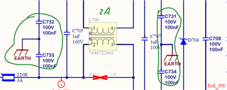
1. The capacitance between VDD-VSS needs to be 50 – 120 nF, and now you have 200nF. Besides, the 100-V Y-cap in the cycles will make the isolation level less than 2kV as C706. It is recommended to not add cap or use 2kV pF level capacitors in the cycled area.
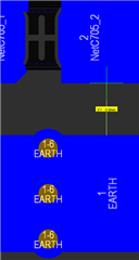
2. The 2kV isolation distance for Earth and ethernet terminal is recommended to be 1.524mm or longer.
3. It is recommended to not have vias beneath the chips center. Especially avoiding the Earth is beneath the chip and has a distance less than 1.524mm.
4. If your current is higher than 1A, 0805 or larger size 0-Ohm resistors are recommended for lower conductance loss and thicker layout wire.
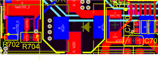
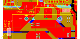
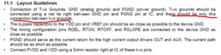
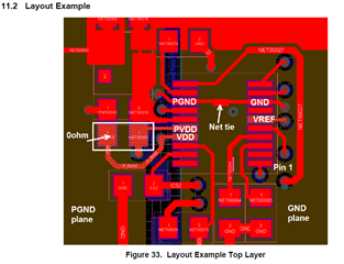
It looks a big concern is GND and PGND connection. The datasheet suggests connect GND and PGND on the two pins underneath the package. Yours is through several layers copper polygons. I suggest you follow the datasheet since the copper polygon planes cannot avoid the current cross flow between GND and PGND which can make noise and affect GND connected weak signals. Suggest only connect GND and PGND at the two pins underneath the IC. The copper polygon for GND only connected to those return paths to GND and the copper polygon for PGND only connected to those return paths to PGND to avoid currents cross flowing to minimizing the associated noise, or more than one loop for a connection which can make ground shifting then another possible noise that very difficult to resolve.
Please make this change and send the changed layout to me for another review.