Other Parts Discussed in Thread: TPS92633-Q1
Tool/software:
Hi Forum,
I got TPS92633Q1-EVM , While trying to understand that EVM, i'm not able to understand few things..
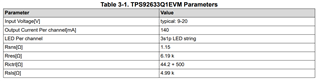
As you can see in page number 5 test setup they mentioned input voltage is 9V to 20V..
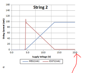
1. As per my understanding, EVM Min Voltage is 9V and Max is 20V... but, the LED is glowing even if i give 4V and when i gave 9V the IC is consuming Maxing current i.e. 440mA
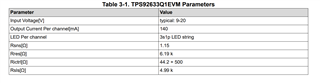
The LED which is used in EV kit says the Vf of that LED is 2.1V means 6.3V is the min Voltage for that IC..
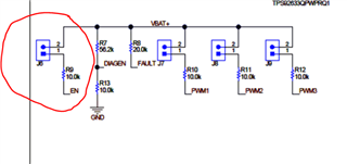
2. For EN pin, can i connect this pin directly to controller pin 5V to ON/OFF with 100Hz frequency ??
Regards,
Tex