


Tool/software:

Hi!
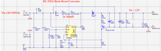
I’m working on a concept where, among other things, I would like to use the low-side Buck-Boost Converter configuration, by using UCC28881D Off-Line Converter from TI. See the attached schematics.
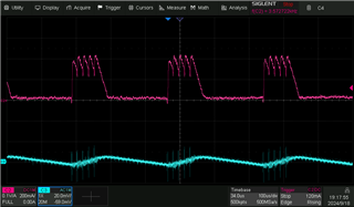
In the test, with attached measurement figures, I have an input voltage of 200V and I’m loading with constant current of 100-mA. I’ve observed that the converter, instead of operating in discontinuous mode, it is running in some kind of burst-mode. In this example I measure an output voltage higher than expected, around 13.7V, but I can easily bring it down to the desired level by tuning the feedback resistors. The good thing is, I can have a constant output voltage throughout the whole load range (0-220mA), but due to this burst mode, it will result in a high output ripple! I can see it stated in the datasheet that it might run sometimes in burst mode, without any further explanation. Can you explain why and when to expect it to run in burst mode?
I suspect it also to be sensitive to noise on the feedback line. Do you have defined any information on possible hysteresis for the feedback input signal? In the datasheet it is only given the threshold voltage (V_FB_TH).
In the attached measurements, the pink waveform is the inductor current, measured with a current probe and the cyan is the feedback (FB) signal (AC coupled to be able to see the slope, measured with a differential probe), measured at a testpoint eTP7.
With best regards,
Gunnar

