This thread has been locked.

If you have a related question, please click the "Ask a related question" button in the top right corner. The newly created question will be automatically linked to this question.

TPS57140-Q1: PH no output

Part Number: TPS57140-Q1

Tool/software:

Hi Expert,

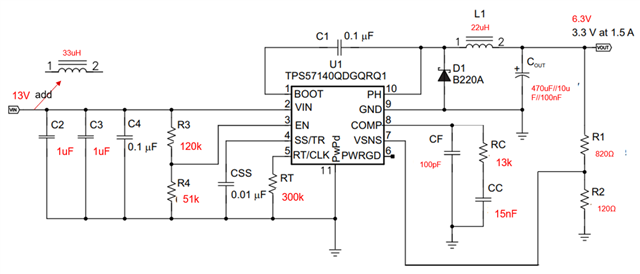
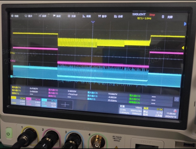
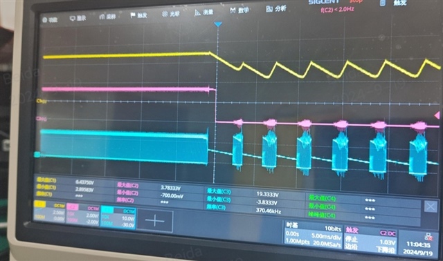
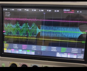
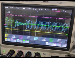
  1. During TPS57140-Q1 work in normal mode, there is no output of PH pin suddenly. Vin and Vout voltage are abrove UV threshold. The left is overview waveform, and the right is zoom in waveform.

waveform description: yellow: Vout; Pink: PWRGD; Blue: PH; Green: Vin.

2. How to calculate the cap value between PH pin and BOOST pin?

  • Hello

    The waveforms look like DCM and/or PFM.  

    Please provide your schematic and your operating conditions.

    Thanks

  • Customer schematic as below, operation condition is Vin=13V, Vout =6.3V.

    Fault Phenomenon: when Iout load is >=0.3A, the Output voltage will drop. When Iout load is <=0.2A, the output voltage is normal. If the load current from 0.3A decrease to 0.1A, the PG will low and turn to High Correspondingly.

    Place a storage energy cap between Vin and GND, the fault disappears.

    Question1: TPS57140 max Iout is 1.5A / 3.3V. Why 0.3A output load can cause the PH no output and Vout drop down?

    Question2: how to select the C1 cap value?

    Question3: how to select CF, CC and RC value ?

     Fault Waveform 1 of 0.3A constant current load, Yellow line---Vout;   Pink line---PG;   Blue line---PH;  

    ZOOM out waveform:

     Fault Waveform 1 of 0.3A constant current load, Yellow line---Vin;   Pink line---PG;   Blue line---PH;  Green line---EN

  • Hello

    If you are using an input filter, as you show, then you will need more input capacitance.

    And some filter damping.

    I would guess that 10uF of input cap, plus a small electrolytic would be a good starting point.

    The other components can be selected using either the data sheet, the calculator tool, or Webench Designer.

    If you can provide images of your PCB layout, we may be able to suggest other improvements.

    Thanks

  • Hi Frank,

    Thanks for your great support! We don't think the PCB layout is the root cause of fault. Because the fault is related to current load directly.

    1. We test 10uF of input cap, the fault disappears. Besides, the fault will also disappear when C1 cap between BOOT and PH changes to 1uF from 0.1uF. Though we check the tools and Webench, we can't find the selection basis for C1 cap. Can you provide the C1 selection theory directly?
    2. The Pin waveform display that the PH experience DCM, CCM, PSM process when fault happens. What's the fault reason in the condition of C1= 0.1uF and there is no 10uF input cap?

    Hope to get your reply in detail.

  • Hello

    1. There are no equations for selecting the BOOT capacitor; the value specified in the data sheet must be used.

    The correct value of BOOT capacitor was arrived at by the Designer of the regulator through device level simulations and

    bench validation when the product was first released.

    2. I assume that the impedance of your input supply is so large that it is causing the regulator to malfunction.  This is 

    especially true if you have the large 33uH input filter.  The large input capacitor tends to lower the impedance at high and moderate

    frequencies.

    Thanks

  • Hi Frank,

    Let's talk it in email.