This thread has been locked.

If you have a related question, please click the "Ask a related question" button in the top right corner. The newly created question will be automatically linked to this question.

TPS25751: development with external mcu and BQ25731

Part Number: TPS25751
Other Parts Discussed in Thread: USBCPD-APPLICATION-CUSTOMIZATION-TOOL, BQ25731

Tool/software:

Dear TI support,

I would like to get update if there has been released any firmware update or workaround to the solution of not working PD source mode of TPS25751 which we described in detail in the end of this thread:

https://e2e.ti.com/support/power-management-group/power-management/f/power-management-forum/1360074/tps25751-development-problems

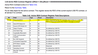
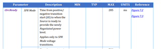
Now we are facing problem, that PS_READY message is sent couple of tens of milliseconds prior to actual ACTIVE_CONTRACT_RDO reg 0x35 update which is when we are able to set correct requested PD profile voltage. In other words, is there a way how to delay generation of PS_READY message?

Thank you

  • Hi Jan,

    Let me check with Conner to see what the status is on this.

    Thanks and Regards,

    Chris

  • Hi Jan,

    Just to confirm, the issue is related to the timing between when Active RDO is updated in regards to the Accept and PSRDY messages? I'm checking internally to see if/how the issues is being addressed. I think another option is to update the register sooner.

    There is not a way to delay the generation of the PS_RDY. We monitor the voltage and the workaround where you apply 20-V may be triggering the PS_RDY.

    The current best option is likely to improve the register update timing.

    Thanks and Regards,

    Chris

  • Hi Chris,

    yeah, that would be great, if ACTIVE_CONTRACT_RDO reg 0x35 would be updated with requested PD profile much sooner than in 120ms after 20V apply. Are you planning to do so? When it will be available for testing in new Application_Customization_Tool?

    thank you

  • Hi Jan,

    Thanks for the confirmation. That solution is currently being evaluated by the team. From the communication I have received, it is currently looking to be 2+ weeks for them develop the feature. Depending on when this aligns with the APP_Customization_Tool release schedule, it could be 1+ months.

    Thanks and Regards,

    Chris

  • Just one more note, it would be great, if ACTIVE_CONTRACT_RDO reg 0x35 would be updated with requested profile number right after PD message REQUEST reception, without the need of setting the OTG voltage to 20V at all.

    thank you

  • Hi Jan,

    The team is still evaluating the issue, but my current understanding is that the RDO register will be updated right after sending the Accept message, which will align with the timing of the Sink Transition Completed interrupt you are currently using.

    I'll keep you updated as I hear from the team!

    Thanks and Regards,

    Chris

  • Hi Chris,

    I noticed new USBCPD-APPLICATION-CUSTOMIZATION-TOOL has been released - Ver 1.0.0, does this version include repaired behavior discussed here, please? If not, is there any update when it will be released?

    thank you a lot

  • Hi Jan,

    The latest GUI does not have the fw fix. I am pushing on the team to provide expected timelines and will update you with that information when I receive it.

    Thanks and Regards,

    Chris

  • Hi Chris,

    do you have some news for us please? We would like to release our product soon and it would be great if it would be fixed by that time.

    Thank you

  • Hi Jan,

    Apologies, no news yet. I'm contacting the team again to provide timelines and updates on progress. I'll push harder for answers.

    Thanks and Regards,

    Chris

  • Hi Chris,

    any news please? It is already more than a month from when you wrote us it could take around 1+ month. We are looking forward to the patch.

    thank you

  • Hi Jan,

    Apologies for the delays. A fix was made and is currently being tested. Testing has been progressing slowly due to challenges involving the testing.

    If you are open to it, I can see if it possible to get you an engineering version of the patch to test on your end.

    Thanks and Regards,

    Chris

  • Hi Chris,

    yes we would like to test the engineering version of the patch if possible.

    thank you

  • Hi Jan,

    Got it, reaching out to the team to get the engineering version. They are in a different timezone so I should expect to get a response by tomorrow.

    Thanks and Regards,

    Chris

  • Hi Chris,

    how is it going with engineering version, please? And when will be available the final version for everybody?

    thank you

  • Hi Jan,

    Sorry for the delays, something came up and this was put on hold. I'll provide you the engineering version tomorrow.

    Can you share your latest json with me so I can build the binary files for you. Also, how are you programming the systemr, do you need the full flash binary or the low region .c file?

    Thanks and Regards,

    Chris

  • Hi Chris,

    we need low region .c file for programming. Json file is attached.

    When will be this solution released to public?

    thank you

    {
      "questionnaire": {
        "device": "TPS25751",
        "answers": [
          null,
          1,
          4,
          4,
          0,
          0,
          0,
          3,
          1,
          1,
          1,
          null,
          0,
          0,
          0,
          0,
          0,
          0,
          0
        ],
        "vendorId": "0000",
        "productId": "0000",
        "version": "1.0.0.2"
      },
      "configuration": {
        "data": {
          "selected_ace": [
            {
              "register": 6,
              "data": [
                0,
                0,
                0,
                0,
                0,
                0,
                0,
                0
              ]
            },
            {
              "register": 22,
              "data": [
                10,
                48,
                0,
                76,
                0,
                4,
                0,
                0,
                0,
                0,
                3
              ]
            },
            {
              "register": 40,
              "data": [
                2,
                0,
                63,
                7,
                0,
                0,
                0,
                0,
                0,
                0,
                0,
                0,
                0,
                0,
                0,
                0
              ]
            },
            {
              "register": 41,
              "data": [
                82,
                80,
                152,
                90
              ]
            },
            {
              "register": 50,
              "data": [
                5,
                168,
                42,
                44,
                145,
                1,
                32,
                44,
                209,
                2,
                0,
                44,
                193,
                3,
                0,
                44,
                177,
                4,
                0,
                244,
                65,
                6,
                0,
                0,
                0,
                0,
                0,
                0,
                0,
                0,
                0,
                0,
                0,
                0,
                0,
                0,
                0,
                0,
                0,
                0,
                0,
                0,
                0,
                0,
                0,
                0,
                0,
                0,
                0,
                0,
                0,
                0,
                0,
                0,
                0,
                0,
                0,
                0,
                0,
                0,
                0,
                0,
                0
              ]
            },
            {
              "register": 51,
              "data": [
                5,
                44,
                145,
                1,
                16,
                44,
                209,
                2,
                0,
                44,
                193,
                3,
                0,
                44,
                177,
                4,
                0,
                69,
                65,
                6,
                0,
                0,
                0,
                0,
                0,
                0,
                0,
                0,
                0,
                0,
                0,
                0,
                0,
                0,
                0,
                0,
                0,
                0,
                0,
                0,
                0,
                0,
                0,
                0,
                0,
                0,
                0,
                0,
                0,
                0,
                0,
                0,
                0
              ]
            },
            {
              "register": 55,
              "data": [
                63,
                64,
                31,
                65,
                144,
                145,
                1,
                0,
                0,
                0,
                0,
                0,
                0,
                0,
                0,
                0,
                0,
                0,
                0,
                0,
                0,
                0,
                0,
                0
              ]
            },
            {
              "register": 92,
              "data": [
                11,
                4,
                0,
                0,
                0,
                0,
                0,
                0,
                0,
                0,
                0,
                0,
                5,
                0,
                0,
                0,
                48,
                4,
                0,
                0,
                0,
                0,
                0,
                0,
                5,
                12,
                0,
                0,
                48,
                0,
                0,
                0,
                5,
                8,
                0,
                0,
                73,
                1,
                0,
                0,
                0,
                0,
                0,
                0,
                0,
                0,
                0,
                0,
                0
              ]
            },
            {
              "register": 112,
              "data": [
                3
              ]
            },
            {
              "register": 152,
              "data": [
                0,
                0,
                0,
                0,
                0,
                0,
                0,
                0,
                0,
                0,
                0
              ]
            }
          ]
        }
      }
    }

  • Hi Jan,

    Please see the attached low region.jan_fixed.c

    Once the feature has been tested and verified, we can pull it into the main release branch. Depending on the cycle for GUI and FW release, this could take days to a month.

    Thanks and Regards,

    Chris 

  • Hi Chris,

    thank you for C file.

    But with supplied low region c file I'm not able to perform patch programming. I get stuck on last step and never get Patch Loaded flag true from Interrupt Event for I2C1 Register (Offset = 14h). Was this file generated for TPS25751 or do you have any other ideas where could be the problem? I can perform patching without any problem with low region C file generated from json file I sent you using USBCPD_Application_Customization_Tool 0.6.0

    thank you

  • Hi Jan,

    I'm looking into this one, I generated the image by loading your json into the 0.6.2 GUI but with a different base image. I can try reverting to the 0.6.0 gui but will need to reach out to the GUI team for access.

    Thanks and Regards,

    Chris

  • Hi Chris,

    don't we need the new version of GUI in order to have there the fix discussed in this topic?

    Thank you

  • Hi Jan,

    Yes and no. It would be better if it worked with the latest GUI, but the old GUI can be modified to support the change I'm trying to make.

    Please try the attached .C file. I think I found the issue related to the image loading properly. This was made with the latest GUI.

    Jan_fixed_1121.c

    Thanks and Regards,

    Chris

  • Hi Chris,

    thank you for this C file, I was now able to patch the device successfully.

    Unfortunately the system doesn't seem to work correctly with this C file. The workaround I describe in thread I point to at the beginning of this topic is not working anymore with this C file. 

    When I remove the workaround and just try to read TPS25751_REG_ACTIVE_CONTRACT_RDO 0x35 register after profile change request and Sink transition completed interrupt I always get requested PD profile number 1 - 5V even if I requested e.g. profile number 2 or 3, 4, 5 (9V or 12V, 15V, 20V).

    I start to be a bit desperate now, do you have any idea of what could be wrong?

    Thank you

  • Hi Jan,

    If I remember correctly, the issue is with the updating of the 0x35 register? Let me push the FW team to review the fix.

    Thanks and Regards,

    Chris

  • Hi Chris,

    yes, exactly, 0x35 register does not update with requested profile number correctly and so it cannot be read out after Sink transition completed interrupt with correct value...

    thank you

  • Hi Jan,

    Thanks, I am confirming with the team about the behavior of the fix.

    Thanks and Regards,

    Chris

  • Jan,

    Which bits are you reading when you read from this register?

    If you check the register much later (snk transition + 50ms), does it get updated? Do you see the register get updated at all?

    Thanks for your responses, I'm working with the fw team to debug this.

    Chris

  • Hi Jan,

    There was some confusion on my end, and I forgot to share some important information.

    Part of the fix included adding extra bitfields to register 0x35. See the image below for the added bit field. The RDO you are looking for should be found in bits 127-96.

    The RDO will follow the PD spec, and should be similar to the 0-31 format, just with a different offset.

    Please try this and let me know how it goes.

    Thanks and Regards,

    Chris

  • Hello Chris,

    I have a good and bed news.

    The good thing is, that it seems, there is immediate update to register 0x35 in the bits fields you described to me - bits 96 - 127. Excellent work, I can finally read out requested profile number immediately after Sink transition completed interrupt without the need of any delays or workarounds.

    The bad news is that there is still some minor bug as it is not working as expected. After power on, my debug SINK device establish contract at 5V (profile number 1), when I request then profile number 2 (9V) it drops the contract and ends up with detach state. If I request any other profile number e.g. 3,4,5 (12,15,20V) then it establishes new contract without any problem and I can be switching through profile numbers as I want - e.g. 1 - 5 - 4 - 3 - 2 - 1 - 3 - 4 -5 - 1 - 4 and so on. Only problem is as I wrote, when I want to switch from 5V contract to 9V contract (1 - 2).

    Would you have any ideas, why is this happening and how to make it work?

    Thank you

  • Jan, 

    For the 9-v state, are you able to read the voltage and program the voltage to change quickly enough? Could you share the logs you sent a picture of? It does look like you are trying to transition to 9-V, but the time scale seems a little unclear.

    From a PD perspective, the only thing we are missing is the PSRDY message, which will come after the source has determined the new source voltage is ready.

    How long does it take for you to send the 9V transition, there is some timing regarding this that needs to be met.

    The PD controller should wait ~25-35 ms before transitioning the voltage (after accept goodcrc) and then has 285 milliseconds to transition the voltage.

    Its interesting that the higher voltage transitions are fine though, as you would think those would be the slowest.

    Thanks and Regards,

    Chris

  • Hello Chris,

    I can transition to 12V, 15V and 20V profiles from 5V profile without any problems, it only occurs when I try to transition to 9V profile.

    Logs are attached. I did 5V - 20V - 5V - 15V - 5V - 12V - 5V - 9V transitions in this log, and error occurs at the end of it.

    I communicate with TPS25751 and BQ25731 over I2C at 350 kHz, so it is pretty fast, I just read 0x35 register and then immediately change the BQ25731 settings.

    Thank you

    2425.logs.zip

  • Hi,

    We have received your message. TI US is closed for the Thanksgiving holiday until Monday 12/02. Please expect delayed responses.

    We hope you have a great rest of your week!

  • Hi Jan,

    Is the 9-V case being handled any differently than the 5->15 or 5->20. I can't think of any reasons why that transition specifically would fail.

    Still reviewing the logs.

    Thanks and Regards,

    Chris

  • Hello Chris and Alex,

    enjoy your holidays and thank you for your support.

    9V case is being handled exactly the same way as the other transitions to 12, 15, 20V.

    Thank you

  • Thanks Jan for your response. Chris will respond as soon as TI US is open on Monday.

    Thank you

  • Hi Jan,

    From the shared logs, I don't see anything unusual. I'm not too sure what is happening here, but have a couple items we can test.

    The 5->9-V transition seems to happen within the required time, and it does appear to be happening correctly.

    Could you share your schematic? From the json you shared, it appears that the 5V source PDO is provided by PP5V, and the other PDOs are provided by PPHV?

    What voltage is PP5V at, and what voltage do you set PPHV to when a 5V contract is negotiated? These should be measured on the board if possible. In the past we have seen issues with RCP triggering if PP5V is higher during the power path transition which can sometimes cause a fault. I'm not sure if this is the case, but is just a though.

    Can you try this .c file? I added the "Power Event Occurred Error" interrupt. Everything else is still the same as before.

    jan_12_2.c

    Do you see any interrupts from the PD controller when the 9-V transition fails? Can you report which ones, and if necessary, read the relevant registers to determine what may have changed?

    Here is another .c File that changes the PDO1(5V contract) to PPHV instead of PP1.

    If possible, please try this one and report if the voltage transitions still work.

    Jan_12_2_PDO1PP3.c

    Thanks and Regards,

    Chris

  • Hi Jan,

    Could you also measure PP5V and VBUS during the 5-9V transition and share the capture? This will help identify if the issue is related to the RCP mentioned above.

    Thanks,

    Chris

  • Hello Chris,

    we tried Jan_12_2_PDO1PP3.c file and things started to work correctly. Excellent, thank you so much.

    Would you like me to do the steps you asked for in order to further investigate why it didn't work with PP1?

    I cannot share the schematic publicly, only if it could be to your private email.

    Thank you

  • Hi Jan,

    Thats great to hear.

    I had some help from a colleague, and we had a suspicion that it could be related to the power paths, we do not need additional debug if you are satisfied with the result.

    For your understanding:

    Originally, your project config worked as in the red case, where PDO1(5-V) was supplied through PP5V and the rest through PPHV. It would switch between power paths when going from 5 -> any other or any other -> 5

    Now it is configured to supply all of them through PPHV. For sourcing, we do need 5-V on PP5V for additional parts of the IC, so the 5-V there is still required.

    For future reference, the changes you needed required a FW change and a Power path change. The FW change was related to the expanded 0x35 Active contract RDO and it's update timing.

    I am working with the team to bring the changes into one of the next GUIs as well as updating the TRM with the register information. It should come within the next month or two, but you should be fine using the provided image. Within the gui, the Tool Release note should indicate if the feature has been added. The change should be related to "Updating Active RDO....".

    Let me know if you have any other questions.

    Thanks and Regards,

    Chris

  • Hello Chris,

    thank you very much for your assistance, we wouldn't be able to solve this without your help.

  • Hi Jan,

    Thanks for your patience throughout the process. I realize it was a bit long with the part change and subsequent FW issue.

    Please reach out if you run into any other issues. When making new threads, reference this one so the assigned engineer can reach out to me if they need additional info.

    Closing this thread now.

    Thanks and Regards,

    Chris