Tool/software:
Hi,
My customer is requesting help with below questions-
- What is the minimum input to output voltage difference required for charging a battery ?
For example, we use a battery pack with 3x Li-ion cells (max cell-Voltage = 4.2V)
The datasheet says that a battery is first charged to certain voltage in with constant current,
then switches over to float charge mode (smaller current, to charge cells to the final level)
When fully charged, our battery pack will be ideally at 3x4.2V = 12.6V.
We have a 13V (+/-5%) power adapter feeding the battery charger.
I am wondering whether the worst case (12.35V) power adapter voltage
(or even the best case of 13.65V) will be sufficient to charge the battery pack.
(Vfb input of the charger is set for battery voltage of 12.37V through Vfb voltage divider)
Usually switching battery chargers that work as buck converters require an input voltage of 2-3V higher than that of the battery they are trying to charge.
There is no such number specified in the datasheet (at least not that I could find, after going through the datasheet several times). All it specifies is the minimum and maximum input operating range (4.7V to 28V)
I need someone to tell me this minimum voltage differential required. - Assuming that our power adapter output voltage is not sufficient to fully charge the battery pack to the target voltage, what will the charger IC do ?
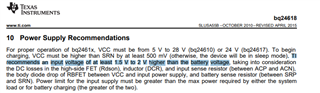
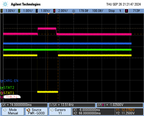
Will it timeout after the set duration and output status as "charging suspended" ? In our system, the battery pack charges to only about 11.4V even though the set point for battery is set to 12.37V, and the charger always ends up in charging-suspended state.
I am wondering the minimum input/output voltage differential is the culprit. - What does the IC do if the set charging current (ISET1) can never be reached because
there is insufficient voltage at the input (VCC pin) to deliver required charging current ?
The datasheet says the duty cycle of the switcher can go as high as 99.5%.
Does it keep max duty cycle and keep going or indicate a fault condition ? - In our case, by the time the battery is charged to about 55-65%, the charger enters into
"charge suspended" mode, that indicates something went wrong.
But the datasheet is not clear about the conditions under which it suspends charging.
I see 7 conditions under which charging is disabled, but not sure these are also the conditions
under which it enters "charging suspended" state. So, I am not clear about what pushed it to suspend charging.
Will it suspend charging (and indicate state as suspended) if
a. CE input is pulled high ? or
b. If thermistor voltage (TS pin) moves into suspend region ? or
c. If the charging timer times out ?
Is there any other reason charging could be suspended ?