This thread has been locked.

If you have a related question, please click the "Ask a related question" button in the top right corner. The newly created question will be automatically linked to this question.

LM51231-Q1: Need confirmation on the quantity of mosfet to be used

Part Number: LM51231-Q1

Tool/software:

Dear Team,
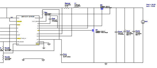
I am designing a 12 to 24V 240W boost converter using the QRGRRQ1 IC. I obtained the attached design from the webench designer tool. However, upon reviewing the EVM, I noticed that they are using a total of 4 MOSFETs, which I believe is for power distribution. Can you please advise me on whether I should proceed with the single MOSFET design or if using 2 parallel MOSFETs would be more advisable? I also have space constraints to consider.

  • Hello Dharun,

    Thanks for reaching out to us via e2e.

    The choice, if you would want to use singe FETs or dual FETs depends on multiple factors: the RDSon of the FETs, maximum current, load profile, cooling concept, space constraints, etc.

    The EVM comes without any heatsink and is rated for 200W. So, we are using dual FETs to distribute the thermal power across the FETs.
    But I can tell that 240W are easily achievable with single FETs if there is some means of cooling the FETs.

    Please be aware that the gate-drivers of this device are pretty strong.
    Therefore, please add some gate resistors in series in the gate lines, no matter if you are using single or dual FETs.

    For a proper calculation of the components, I would recommend using the QuickStart Calculator, which you can download from our product website:
    www.ti.com/.../SLVRBJ1

    Best regards
    Harry

  • Thanks for the reply. I'm using a zero ohm as gate resistance which i got from tool. But im going with the output capacitor of only 100uF while the suggested is 220uF. Hope it will not give any problem. 

  • Hello Dharun,

    With single FETs you will probably need to use some gate resistors between 2 Ohm and 5 Ohm.
    But this depends on your FETs (how fast they are switching).

    Please have a look at the switch node with an oscilloscope and verify how much ringing you will see there.

    Make sure that you will use the same resistor value for both driver outputs and do not go above 5 Ohm.

    Best regards
    Harry

  • Hi Harry,

    Thanks for the inputs it will be really helpful. But, I'm not having the time to probe and check the ringing. So, I'm going with something in between 2 to 5 ohms.

    Also, this maybe a newbie doubt but i wanted to confirm whether I can use the same compensation as that of the EVM or i should only go with the values suggested by calculator tool.

  • Hello Dharun,

    For the compensation network, you should definitely use the values suggested by calculator tool.
    Otherwise, the system may be unstable.

    Not checking the ringing is a dangerous approach.
    If the resistors are too small and the undershoots are too big, this will break your controller.
    If the resistors are chosen too big and the FETs are also switching slow, you may get cross-conduction and your FETs will break.

    So, please take an oscilloscope and have a look at the switch node and the two gate signals to verify if there is no such issue.

    Also, please follow the layout guidelines in the datasheet.

    Best regards
    Harry

  • Hi Harry,

    Thanks for the point. I will probe the SW for ringing or else i will check if it is possible to go with the 2 FET design. I hope by that way no issues will be there.