Tool/software:
Hi,
I'm using LMG1210 as half bridge driver in one of my applications in which I want switching frequency is between 1-1.5MHz. For cost saving I'm using AOD2544 MOSFET instead of using GaN FET. In half bridge configuration as provided in the LMG1210EVM-012 board, the MOSFET switching losses are very high. For average load current of approx. 1.5A with 100V as VCC, each MOSFET dissipates approx. 5W of power as per the Spice simulation and also in real life. To minimize the miller plateau effect, I've come up adding 10+10 ohm power resistors between high side and low side MOSFETs. Now the MOSFET's power loss is minimized to approx. 400mW on same load. Ignore the power loss in power resistors because that power resistors are necessary part of my load circuit.
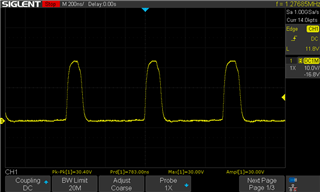
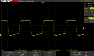
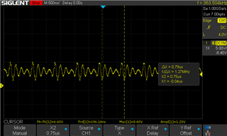
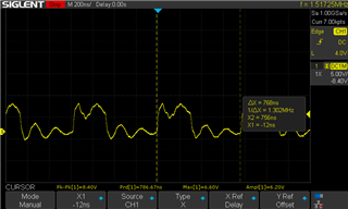
My question is, can I design circuit like this? (Refer shared schematic). The circuit is working fine. But as the 5W resistors were heating more, I replaced them with 10R 50W aluminum casing resistors (just for testing). Power loss isn't concern, heating is. The resistors are very large in volume, so I placed them with the help of 10cm wire pieces with the board. By doing so, my LMG1210 IC blown up. I rechecked everything with onboard 5W resistors and again replaced 5W resistor with 50W big resistors and again LMG1210 IC blown up. Is there any specific reason? With that power resistors I didn't even go with 100V capacity. I increased voltage only up to 20-30V. But IC stopped giving proper outputs. And both the time, the low side switching was functioning properly, only high side driving section was damaged.


