This thread has been locked.

If you have a related question, please click the "Ask a related question" button in the top right corner. The newly created question will be automatically linked to this question.

TPS2660: Reverse current blocking not working

Part Number: TPS2660


Tool/software:

It is my understanding from the datasheet that TPS26600PWR is supposed to be reverse current blocking, but it does not appear to be working for some reason so I would really appreciate some assistance please.

Description of the application:

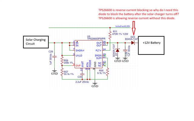
Please refer to the attached schematic.

On a clean power up the reverse current blocking is working.
I turn on the solar charging circuit and the battery starts charging properly.
I turn off the solar charging circuit and remove all power(disconnect the power wire), but the battery voltage is leaking back enough to keep my status LED turned on saying that it is still charging. 
If I only turn up the charging voltage to 10 volts the charger won't start charging yet, but 10V will be on the input of the eFuse and I can remove this voltage and the eFuse will keep bocking reverse current after the 10V is removed. 
So it is only happening after the solar charger starts charging then stops.  I am charging with 150-800mA at around 12V up to 14.4V. 
If I put D23 in the circuit then the reverse current is blocked properly so why isn't TSP26600 blocking the reverse current properly? 
I cannot use this diode in my application so I need a true current blocking eFuse.

Your help is greatly appreciated. 

Thank you,
Gary 


  • Hello Gary,

    Thanks for reaching out to E2E.

    What's the reverse current leakage you are seeing?

    You can check the reverse current threshold below.

    Can you tell me your system requirement (max VIN,Max ILoad)?

    Thanks 

    Amrit 

  • The datasheet says 60uA reverse current so that would be acceptable.  I didn't actually measure the reverse current with the 378k resistors as per the schematic, so it is assumed to be 29uA when the battery was at 11V.  So do I need to increase this to 60uA to get the blocking to work? 

    I don't think that will work because I did a test and put a 1k load resistor on Vin pin so it drew 11mA reverse current and TPS26600 did not block it.  I put a 51 ohm resistor which drew 215mA and then it blocked it but I can't put a 51 ohm resistor on the efuse input or that will steal all my solar power and the battery won't charge.  This is why I'm running out of ideas feeling like I'm at a dead end. 

    System requirements: 
    As I mentioned in the original post, the battery is operating at 10-14.4V typically charging at around 100mA to 800mA but could peak to 1.5A  
    The charging voltage will run a similar range but will stop charging at 14.4V.  The battery could die and drop to around 8V so that is why I don't have a low voltage cut off because the solar charger will trickle charge the battery to try get it to recover if the battery voltage drops that low.   As you know, solar power is only available during sunlight hours of the day and the voltage will drop to 0V at night so the input of the efuse voltage will range from 0V to 14.4V based on the available solar charging voltage. 

    I hope that helps clarify the functionality a little more?

    Thank you.
    Gary 

  • Amrit:
    I just ran another test to try determine V(FWTH) and V(REVTH). 

    I removed D23 and put my ammeter in series there to measure the current only on the efuse.

    Test 1: 
    On cold boot when the efuse is blocking:
    Vin = 0.113
    Vo = 11.66
    Therefore, V(RevTH) = -11.547 (gnd probe on Vin and + probe on Vout) 
    reverse current in this state is 5.3uA 
    Note - this is working correctly and is blocking reverse current 

    Test 2:
    After test 1 is completed, then I turn on the solar charger and apply 800mA charge current.  Battery is around 11.7V 
    I turn off the solar charger to 0V and measure: 
    Vbat = 11.68
    Vout = 11.68V 
    Vin = 11.68V

    Therefore V(RevTH) = 0V
    So I put my voltmeter on lower scale across Vin and Vout (gnd probe on Vin and + probe on Vout)
    and V(RevTH) measures 0.8mV 
    Ammeter is measuring reverse current from Vout to Vin at 3.5mA.
    Solar voltage supply is completely disconnected so 0V @ 0mA from the charger

    When Solar charger supply was connected then the reverse current from Vout to Vin will be round 14mA so that is why I disconnected it to see if it has an affect and it actually draws more reverse current when connected.  Hence the reason for needing reverse current blocking efuse or it will kill the battery. 

    I don't know why the eFuse is letting through so much reverse current? I hope this gives you some more insight into what is happening here? 

    I appreciate your help on this matter.

    Thank you,
    Gary 


  • Amrit
    I ran some more tests today trying to narrow down this issue and find a solution:
    - I suspected maybe I needed undervoltage to detect and block the reverse current
    - I also suspected maybe the solar charger is causing issues

    I used another TPS26600 circuit I have that has UVLO configured and setup in circuit breaker mode.  Refer to schematic below.
    I connected a current limited variable power supply to Vin to emulate the solar charger 

    Results:
    It operates the same as my original circuit. 
    Reverse current is not blocked from the battery when Vin drops below Vbat and it is also not blocked when Vin goes below UVLO. 
    - reverse current is blocked on cold boot when Vin is 0V and while lower than UVLO
    - if I slowly turn up Vin and it starts forward conducting to the battery the current flows from Vin to Vout then reverse current blocking will not be disabled when Vin voltage drops below Vbat.  This is the same issue from my original post and this circuit is doing the same. 

    Conclusion:
    I'm guessing the TPS26600 reverse current blocking needs to be turned on/off somehow and I'm missing something in the datasheet  that turns it on when there is reverse current being applied greater than 60uA. 

    Please help me understand this mechanism so I can get my circuit to work properly.  

    Thank you,
    Gary 

  • Hello Gary,

    What's the voltage difference between VOUT and VIN?

    Also, you have shorted SHDN pin to VIN. You can keep SHDN pin open since it has internal pull-up.

    When VIN-VOUT goes below -10mV, reverse current blocking works.

    you can calculate the min current by dividing with RDSon.

    Thanks 

    Amrit 

  • Amrit:

    I have concluded the voltage and current on Vout is flowing back to Vin and not allowing Vin-Vout to drop to -10mV to block the reverse current and it is staying at 0V.  Therefore I do not see how the TPS2660 can do reverse current blocking if the reverse current is disabling the reverse current blocking feature?   


    Please see my results provided for test 1 and test 2 above.  As I mentioned above, after the solar charger power is removed then the voltage between Vout and Vin is 0V and it is like the efuse is latched up allowing reverse current flow.  Whatever voltage is on Vout will flow through to Vin so it will never get -10mV and in this state it will easily allow excessive reverse current 11mA or more so it is not a floating voltage either - it is drawing reverse current from the battery.  I even put a pull down resistors on Vin in case the Vin voltage was floating but that does not help either except the 51ohm resistor got it to work as I mentioned above. All this is already explained in the thread above so why is the TPS2660 latching up like this and how do I get it to unlatch? 

    As per your suggestion, pin 7 SHDN# is open now so it will use the internal pullup - no difference in operation.  As per my notes above - I even tried a different circuit using UVLO and there is no difference.  

    The only way I can get this circuit to work is to put an external blocking diode in series (not permitted for my solar charger design) but the datasheet is very clear the external diode is not needed and that is one of the benefits of using this component. 

    Would it be possible to get technical support on a video call please?  It's been almost a week and we are not making much progress here. I need this resolved ASAP please. 


    Thank you,
    Gary 

  • Hello Gary,

    TPS2660 doesn't have true reverse current blocking.

    min reverse current to be detected TPS2660 would be 10mV/150mOhms = 66.7mA

    11 mA reverse current won't be detected by TPS2660. 

    Let me know if you require further help.

    Thanks 

    Amrit 

  • Amrit:
    If that is the case then TPS2660 datasheets are EXTREMELY misleading!  See attached page 19 and 20 from the TPS2660 datasheet and tell me how I misunderstood this?  The TPS2660 datasheets clearly says the external diode is not needed for reverse current blocking so that is why I specified this device into my design. It is also clearly stated several times throughout the document. 

    This makes me loose trust in the rest of the TI efuse datasheets so can you please tell me which efuses "have true reverse current blocking" and how can I identify which datasheets I can trust?  As a result of TI's negligence, now I have to redo my design so please provide me a list of similar efuses with true reverse current blocking.

     
    Thank you,
    Gary 

  • Hello Gary,

    Sorry for your trouble.

    Reverse current threshold is mentioned in datasheet. TPS2660 does have reverse polarity protection as shown in figure-35.

    By true reverse current blocking feature, I meant reverse current blocking like diodes.

    TI ideal diode solution and High side switching does have this.

    Let me know your system requirement for me to suggest the device.

    Thanks 

    Amrit  

  • Amrit:
    I can't believe you would refer to figure-35 to support the TPS2660 saying it has reverse polarity protection when I just roasted figure-35 as being "EXTREMELY misleading" because that clearly says an external diode is not needed but that is FALSE!! A diode is needed!!! 

    How can I determine from the datasheets which efuse is "fake" reverse current blocking and what is "reverse current blocking like diodes" because I haven't seen any data sheets that say "reverse current blocking like diodes" and they all say the same thing "reverse current blocking" so how can I determine which datasheets are misleading and which ones are truthful? 

    My system requirements are mentioned in the thread above but to be more clear, I require something like the TPS2660 with "reverse current blocking like diodes" but I would prefer something with higher current rating like 5A so it can have a lower rds value.  TPS2660 is perfect in all ways and it is working perfectly in my prototypes except it is not true reverse current blocking so that is my only issue.  

    Please advise on an appropriate alternative. 

    Thank you,
    Gary 

  • Hello,

    Sorry for your trouble Gary.

    I will certainly bring this to TPS2660 datasheet correction.

    I can propose two alternate solutions for your system considering 12V nominal.

    1. TPS25948xx 3.5V–23V, 12.2mΩ, 8A eFuse With Bi-directional Power Delivery.

    Feature: diode operation with true reverse current blocking (RCB) – External pin control (RCBCTRL) to disable RCB and allow bi-directional power delivery.

    2. TPS2660 + LM73100, LM73100 is an ideal diode with integrated back-to-back FET with true reverse current blocking.

    Thanks

    Amrit