This thread has been locked.

If you have a related question, please click the "Ask a related question" button in the top right corner. The newly created question will be automatically linked to this question.

UCC28951-Q1: Abnormal waveform of transformer

Part Number: UCC28951-Q1
Other Parts Discussed in Thread: UCC28951

Tool/software:

Hello,

I am designing a phase shifted full bridge circuit using the TIDA-020031 reference design, with an output voltage of 70V, a current of 45A, and a maximum power of 3000W.

The transformer turn ratio is 2:1, shim inductor is 9uH, the output inductance is 42.8uH, using a current doubling rectification scheme.

I disabled the E and F outputs of UCC28951 during testing.

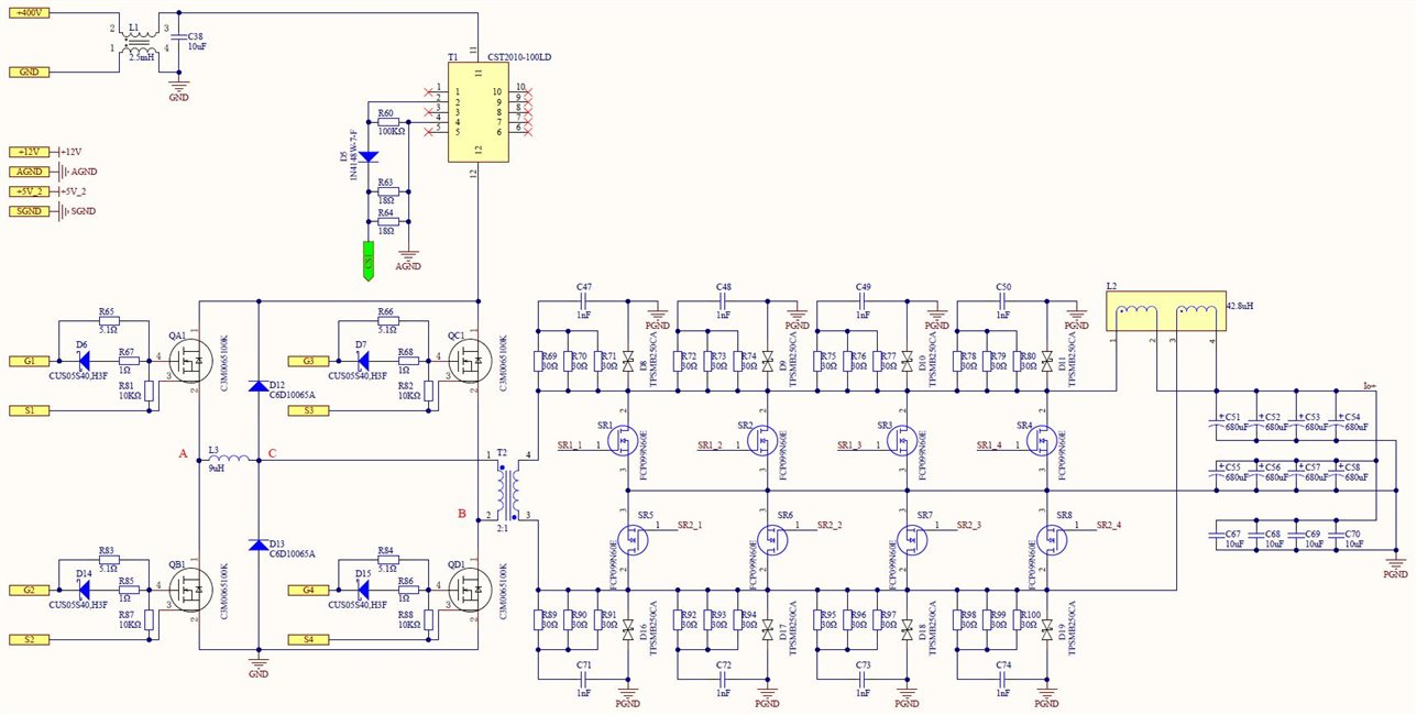
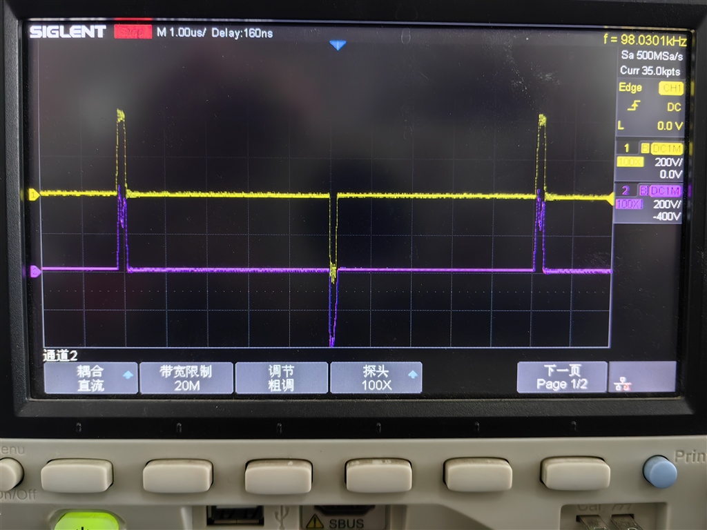
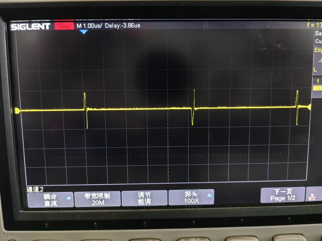
The current problem is that the voltage of the shim inductor Uac almost follows the voltage of the midpoint of the bridge Uab, resulting in abnormal primary voltage of the transformer Ubc. The figure 1 shows the actual waveform tested, channel 1 (yellow) is Uab, channel 2 (red) is Uac. The figure 2 shows the waveform of Ubc. At the same time, the temperature rise of D12 and D13 is very severe. 

I would like to know if there are any design errors and if UCC28951 is suitable for a 70V output DC-DC.

Please help me.

  • Hello,

    Your inquiry is under review and I will reply to you shortly.

    Regards,

  • Hello,

    I reviewed your partial schematic and it looks O.K.  You should check the OUT A through OUT F and gate drive connections to make sure they are correct. The following link will bring you to an application note that goes through the step by step design process of a phase shifted full bridge using the UCC28951.  There is a schematic of a 600 W reference design that you can use to verify your connections.

    https://www.ti.com/lit/pdf/slua560

    Your voltage across the primary of the transformer is roughly the same amplitude as the voltage across the shim inductor.  The only way this can occur is if your shim inductor is equal to the primary inductance of your transformer.  To reduce the voltage drop across the shim inductor you either need to increase the magnetizing inductance of the transformer or decrease the inductance in the shim inductor.  I agree that having a 50% drop in voltage across the shim inductor will create issues for your design and needs to be resolved.  Application note Slua560 give guidance on sizing Lm and Ls for your design as well.

    Your duty cycle does not look correct for your design.  With a 400 V input and a 70 V output and a turns ratio of 2 to 1 your duty cycle should be 35% and yours is much lower than that.  If there was a large voltage across your shim inductor, this would cause your duty cycle to be even higher than 35%.  I think you might be tripping cycle by cycle current limit and your output most likely is not in regulation.  You can verify this by studying your current sense signal, voltage amplifier output, output and CS pin to verify. 

    If your design is going into over current when it should not your CS transformer and CS resistor may not be setup correctly.  You can use application note slua560 to check this setup as well and adjust as necessary.

    If your current sensing is correct and your design is not regulating due to cycle by cycle current limit.  This could be cause by CS noise.  You can resolve this will low pass filter from the CS resistor to the CS pin.  If this is the case you can start with a 1 k ohm 220 pF filter and adjust the pole filter as necessary.

    fp = 1/(2*3.14*R*C)

    If your clamp diodes are getting hot they may not be rated for high enough power.  Consider using diodes rated for high power to lower the power dissipation.   

    You can use a UCC28951 for a 400 V to 70 V 3 kW output.  The following link will bring you to an application note that goes through the step by step design process of a PSFB using the UCC28951.  There is also a link with and excel design calculator that goes along with the application note.  You can use both these tools to help do the design and/or check the design as well.

    https://www.ti.com/lit/pdf/slua560

    Thank you for interest in Texas Instruments (TI) products.  If you have a related question, please click the "Ask a related question" button in the top right corner. The newly created question will be automatically linked to this question.

    Regards,

    Regards,