This thread has been locked.

If you have a related question, please click the "Ask a related question" button in the top right corner. The newly created question will be automatically linked to this question.

UCC28740: NO OUTPUT

Part Number: UCC28740

Tool/software:

Hi team,

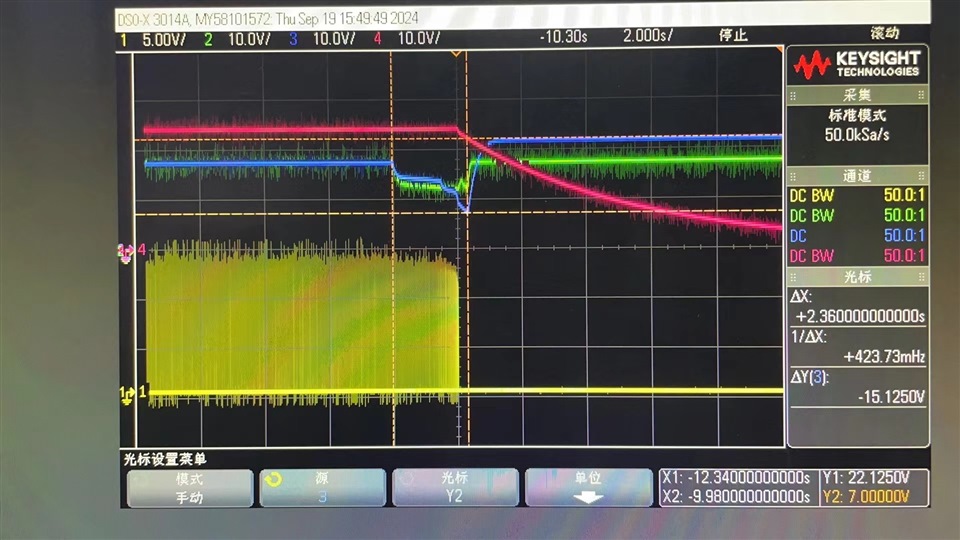
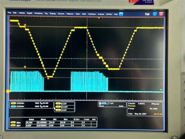
The customer designed flyback using the UCC28740, the following figure is a cut-off HV input test for light loads of two UCC28740 boards. 

Customers find that some of the boards’ UCC28740 stops output when VCC drops to UVLO off after the INPUT is cut off, but the VOUT does not output after VCC recovers. 

Assumption for the customer:  When VCC reaches UVLO on, iso-output does not fall to 0, does that trigger some protection of the IC to turn off VOUT? 

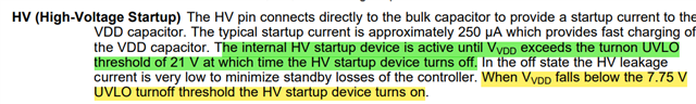
My assumption: Customer configuration rated VCC=22V, UVLO on max 23V specified in DS, is there some probabilities of the UCC28740 not turning on at 22V VCC? However, customer feedback: The UCC28740 in the picture below is also able to turn on the 21V VCC. I don't know if UVLO on  is a small range change? 

Due to the special circumstances, the customer is inconvenient to test more data, and we need to provide some possible conjectures first. 

Green: board 1# VCC of UCC28740; Blue: board 2# VCC of UCC28740; Red: board 2# flyback iso-output; Yellow: Vout of UCC28740

  • Morty, I have some follow up questions for you:

    -First, are you cutting off VINP and then turning it back on immediately?

    -Do you have this issue just at no load or also at some and/or full load?

    -Why is there two (VCC-GND) signals for two boards? Are you testing two different boards separately? 

    -Just to confirm, DRV-GND output belongs to green or blue signal?

    -Green VDD is <20V (assuming the green reference in the scope is behind the red 4 channel, difficult to tell) and UVLO for UCC28740 is 21V typical value.

    -Blue VDD is ~21V but difficult to tell exactly. 

    After the question I can come back on Monday with a clearer answer.

    Thank you

  • Hi,

    I found that no DRV pwm appeared to be due to the customer not using HV pin but a traditional high voltage resistor to turn on. 

    I disconnect the HV pin of UCC28740EVM from the HV DC input and leave the HV pin floating like customer use. The VDD pin uses an external supply to simulate the high voltage startup resistor to reproduce the customer's fault. 

    DS description HV will start working when VDD drops to UVLO off, but if HV floats it appears that the UCC28740 does not recognize the voltage supplied directly to VDD pin by the external power supply, even if it has exceeded UVLO on. 

    Yellow: VDD pin(powered by external voltage supplied)            Blue: DRV pin

  • Hi Morty,

    -Regarding HV startup: It stops when VDD ramps up to UVLO_ON 21V and it turns back on when VDD reaches UVLO_OFF 7.75V (see below from DS)

    -According to your waveforms, at the beginning DRV provides switching pulses and then it stops when VDD falls to ~6V and returns back to switching when UVLO ramps up to ~21V, then another cycle of switches stops when VDD falls ~8V and then no more switching.

    -Is this working when HV connected is HV line?

    Thank you