This thread has been locked.

If you have a related question, please click the "Ask a related question" button in the top right corner. The newly created question will be automatically linked to this question.

LM5025: Circuit improvement issue

Part Number: LM5025

Tool/software:

Hi,

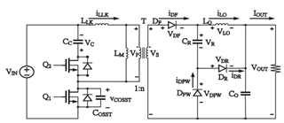
I found a method to reduce the voltage spike on the secondary side diode of an active clamp forward converter and would like to apply it to the LM5025. Is this feasible?

His method uses diode rectification, while the LM5025 uses synchronous rectification, so I'm not sure if it can be implemented.

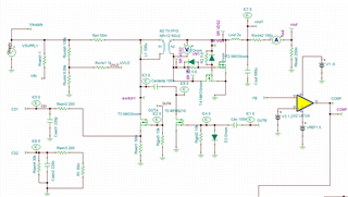
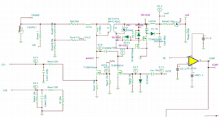
The circuit modification is as follows: CR and DR have been added.
  • Hi,

    LM5025 converter secondary side is ok to use didoes for rectification and synchronous rectification. If this method is ok to do so then it is ok to use with LM5025. 

  • Hi,

    Thank you for your response.

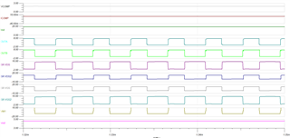
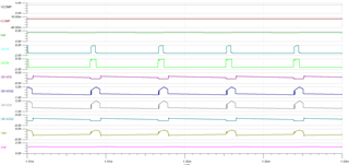
    After simulating the circuit in TINA, I found that my output voltage dropped from 5V to 1V, and the conduction time of OUT_A and OUT_B significantly decreased.

    Could you please advise on the possible causes of this issue?

    The first figure shows the waveform of the circuit without the snubber, and the second figure shows the waveform after adding the snubber.

  • Hi,

    I suspect C1 in your circuit is not big enough so not enough current to freewheeling, you may check. But it is better to talk to the people who created this approach to see what else needs to adjust.

  • Hi,

    I tried increasing the size of C1, but it did not make any difference. Additionally, I noticed that the COMP voltage is higher than the normal operating voltage and has reached the COMP open-circuit voltage level.

    Could this be the reason why it is not functioning properly?

  • Hi,

    Higher COMP should be from Vout not get into regulation. I am not fully understanding this method - please talk to the people who made this method for support.