This thread has been locked.

If you have a related question, please click the "Ask a related question" button in the top right corner. The newly created question will be automatically linked to this question.

LM5036: Power management forum

Part Number: LM5036

Tool/software:

Hi, 

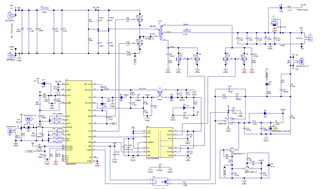
I am using LM5036 for my design conditions

Vin:20-95V, Vout:13V, Iout:30A

Using LM5036 EVM schematic as reference. 

Just had few technical questions regarding the working, etc. I have gone through the datasheet and other technical material, but still some doubts - If you can help explain that will be of great use to me

a. can you share what is the value of Vaux1, Vaux2  and Vx in the EVM schematic?

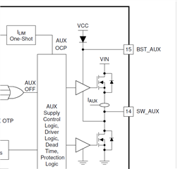
b. Can you help explain the startup operation and then Vcc taking over by AUX supply- my ques is how can AUX supply output Vcc when Vcc itself is needed to power the gate drivers as we can see from functional block diagram? There should be an existing Vcc already for flybuck operation to even start. Please correct me here.

c. Can you also help explain in brief RESET connection which i used in the level shift detection circuit and then connected to D7 and R14. 

Thanks a lot, 

(I might ask other minor questions over other components used in the schematic as I work on my design going forward so will use this thread to converse with you)

Sahil

  • Hi,

    a.

    Vaux1, 8.5V, Vaux2, 8.5V, Vx, 4.7V

    I suggest to obtain an EVM to check out.

    b.

    Please review Fig 7-9 and associated content of the datasheet.

    c.

    Refer to Fig 7-9, Vaux2 is 12V for a short time, turn on Q7A, Q78, to discharge C21, and turn on D7, through R15, to provide a small current to C19 and C18 to neutralize its possible charged voltage (left + and right -) to 0, or to (left - and right +), so to help the startup with 0 duty cycle when Vaux2 change to 8.5V. Startup with 0 duty cycle to help smooth Vout turn on to avoid Vout jump up or overshoot.

  • okay Hong, thanks. I will check point b)

  • Hi Hong, do we have equation for calculating Lmag(main transformer)? Could not find it in datasheet or in excel calculator? it is assumed to be 70 uH. thanks. 

  • Hi,

    It is a half-bridge converter so it is designed based on the half-bridge converter. For example, you can refer to the below.

    Power Topologies Handbook (ti.com)

  • Hi Hong Huang, in the handbook - it does not give calculation for Lp. It only gives equation for Lsec which is based on Lp and turns ratio

    There is still that Imag which either needs to be assumed i guess for Lp calculation. please help. 

    Thanks, 

  • Hi,

    You need to decide Imag, usually you can assume a few percent of the full load current at primary, say 1%, or so, then you can calculate Lp. So basically you need to design the converter first then design the Lm after you know t1. Imag is a trade of the size, cost, etc. In half bridge small Imag is preferred then size and cost are on your choice. Typically for LM5036 Lm is 1mH or less as a reference for you.

  • great thanks for the quick guidance :) this will be helpful

  • Hi,

    You can also take this for half bridge transformer design

    e2e.ti.com/.../half-bridge-transfomer.pdf

  • great, thanks for the confirmation - yeah i had downloaded it few days back!

    excellent!

  • Huang, one more ques, I see in most of TI LM5036(half bridge designs) - fsw of primary side MOSFETs is kept to be 200kHz. 

    Can I operate at 100 kHz primary side MOSFET? - the reason being I want to reduce reverse recovery losses on secondary side MOSFET. 

    other thing is by default in TI LM5036 excel calculator, default fsw is 200k, just wondering if the calculator will work fine if I change fsw to 100 k in the calculator?

  • Hi,

    Switching frequency fsw = fosc/2, when fsw 200kHz, fosc = 400kHz. But when fsw = 100kHz, fosc = 200kHz. Based on Figure 6-5, the IC fosc is at very its recommended min conner fosc - you can try but may show some issues such as the accuracy of fosc gets less. Switching frequency 200kHz is most used in the 48V input (36V to 75V) applications which means 400kHz fosc. That is why the datasheet has a specs at 200kHz. Lower than 200kHz, it is not common in 48V applications. 

  • thanks Huang for your super quick and detailed reply. This makes sense...

    one more final ques i suppose from my side - 

    My design requirements are causing high stress and losses on sec side MOSFETs  with existing MOSFETs (by doing theoretical calculations and using TI excel calculator LM5036 half bridge)) - hence I might have to use 4 parallel MOSFETs for SR1 and SR2 each. (that means 8 SR MOSFETs in total)

    My ques is as I am using TI EVM for reference which uses UCC21225(4A/6A) gate driver to drive SR MOSFETs - will this driver be sufficient to drive so many MOSFETs in parallel? I have seen TI reference design PMP40500- https://www.ti.com/lit/df/tidm136/tidm136.pdf?ts=1727201757244, where the external gate driver is driving 6 SR MOSFETs total(3 each for SR1, SR2 respectively). 

    I am fine with 3 parallel MOSFETs each, just not sure if I move from 3 to 4, will there be any issue with driving using UCC21225?

    thanks a lot once again for your great technical support. 

  • Hi,

    First you need to provide the MOSFET part numbers to use for parallel, and their datasheets. Second this is a question to ask a different support so I suggest you to create a new thread subject such as can UCC21225 drive four MOSFETs in parallel of each its output? Also specify fsw, bias voltage etc.

    This new thread will reach that particular support team to help.

  • Thank you, I have almost completed my design schematic and in review stage using TI excel calculator LM5036 - half bridge. 

    One final query - input half bridge capacitors(C3+C4+C5+C6) - my values for the 20 A and 30 A design using TI excel calculator come to be 130 uF and 195u. As my Vinmax is 85 volt, so I will chose 50 volt rating for each capacitor..The issue is I am unable to find high ceramic capacitor values with 50 Volts rating on digikey. 

    Can you pls suggest some help? Can i parallel more caps to meet my requirement. 

    thanks a lot, 

    20 A design

    30 A design

  • or I can use electrolytic also to meet my requirement? is there any issue if I use electrolytic and not ceramic. mostly I have seen ceramic getting used in half bridge capacitor designs. 

    thanks

  • Hi,

    You can parallel ceramic capacitors to get the capacitance you need. Electrolytic type is not good since its frequency is low. Usually the switching frequency is 200kHz, electrolytic capacitors cannot be used or they become very hot or not able to provide corresponding current.

  • Thanks Hong, got it. thanks for your technical help.