UCC21520: The UCC21520 output is faulty

Part Number: UCC21520

Tool/software:

I am a student of power electronics. When testing the driver chip UCC21520, I found that as long as the power supply pin VDDA on the output side is powered, there is no signal on the input side. The output OUTA is a high level, the amplitude is the same as the power supply, and changes with the power supply voltage, but OUTB is not affected, I measured the VDDA and OUTA with the on-off switch of the multimeter, and found that there is no short circuit, so what is the situation? How to solve it? (INA low level, INB high level, resulting in OUTA signal, OUTB no signal, of course, OUTA amplitude is still the same as VDDA)

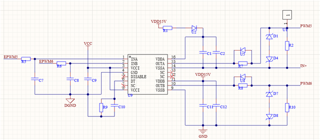
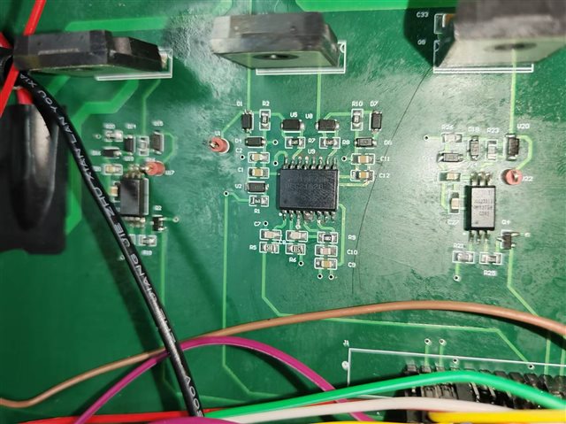
  •  This is my schematic and physical PCB

  • I said wrong before, is that as long as the output side of the power supply pin VDDA power supply, no matter whether the input side of the signal, the output OUTA is high, the amplitude is the same as the power supply

  • Hi,

    Thank you for your interest in our devices and reaching out with your questions.

    Taking a look at the schematic/board, there does not seem to be any clear concerns.

    Just to understand this a little more, I have a couple of questions:

    • Have you tried to swap the driver and/or swap the board to see if this is an issue with the driver or board?
    • Does this occur on channel B at all?
    • Could you share waveforms of INA/INB/OUTA/OUTB for the following:
      • INA held low; INB switching
      • INA held high; INB switching

    Looking forward to hearing back!

    Regards,

    Hiroki

  • hi,I'm sorry it took so long to reply to your message

    The OUTA output is not much of a problem at the moment, although it will go up after switching on VDD15V, but it will return to normal once I turn on my DSP controller (i.e. switch on VCC5V).

    But now I have other problems. When I input complementary 3.3VPWM waves to INA and INB, I find that OUTA can normally output 15VPWM waves, while OUTB has no output, and the voltage on the OUTB pin is 0.

    Then I saw someone else's post about UCC21520 in the TI forum and found that VSSB and OUTB short-circuited, while my two clamping diodes D7 and D8 were normal, so I guessed that the chip was accidentally damaged.

    If you have different views, I would appreciate it!

    Regards,

    CaiLI

  • No problem, thanks for following up.

    The OUTA output is not much of a problem at the moment, although it will go up after switching on VDD15V, but it will return to normal once I turn on my DSP controller (i.e. switch on VCC5V).

    Depending on the output structure of the controller, INA may be getting pulled up past the turn-on threshold voltage. Have you tried adding a pull down resistor to see if this resolves this issue?

    For getting no signal on OUTB, this does seem like some loss of functionality on that channel. When removing the driver from the board, how do the B channel pin impedances look?

    • VDDB - VSSB, OUTB - VSSB, VDDB - OUTB

    This will tell if there was some damage and also give an idea on how it was damaged.

    Looking forward to hearing back.

    Regards,

    Hiroki

  • Thank you for your reply. I'm sorry for not being able to reply in time due to the time difference.

    In the absence of a drive signal, I tested the impedance of the OUTB related pin as follows:

    VDDB-VSSB: 258 ohms
    OUTB-VSSB: 0Ω
    VDDB-OUTB: 260 Ohms

    Out of curiosity, I tested the associated impedance of a brand new UCC21520 (without access circuit) :

    VDDB-VSSB: 1.1MΩ
    OUTB-VSSB: 1.4MΩ
    VDDB-OUTB: 1.7MΩ

    Does this mean that the UCC21520 chip in my circuit is broken?

    Looking forward to hearing back.

    Regards,

    CaiLi

  • Hi CaiLi,

    Thank you for looking into my requests. That is very helpful information.

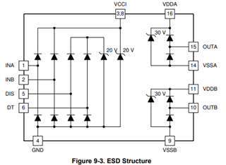
    The impedance measurements definitely show EIPD in the B channel output stage. The measurements on the known good UCC21520 unit is what is expected. The affected unit shows damage most likely in the ESD diodes of the output stage in the B channel.

    This can happen by accidentally shorting the pins together (sometimes happens when probing with the device powered up). In application, this type of EIPD happens typically by noise on these pins or the signals on these pins exceeding abs max specifications (causing these diodes in the figure to conduct).

    Do you know if this damage occurred accidentally? With a good driver placed on the board, does channel B get damaged again?

    Hopefully this was an accidental damage to the driver and a good unit performs without issues. 

    Please let me know if there are any issues when replacing the damaged unit.

    Regards,

    Hiroki

  • Thanks. I fixed the problem with a new chip