This thread has been locked.

If you have a related question, please click the "Ask a related question" button in the top right corner. The newly created question will be automatically linked to this question.

TLV61048: Mean of VBAT and about Pspice for TI model

Part Number: TLV61048
Other Parts Discussed in Thread: TPS63070, TPS61033

Tool/software:

Hi team,


I have three question about this product.

①In datasheet figure 1, it is said VBAT is Powe Stage Input. In my understanding VBAT is bias input voltage(Bias VIN) said in figure 7. So figure 1 shows the efficiency when separate input voltage to VIN and Bias Vin like figure 7.

Is it correct?

②In Pspice for TI Transient model, it is said SS time can adjust by changing value of "SS_CURRENT". In my understanding, this value is internal current source value on SS or REF in 7.2 Function Block Diagram.

SS time is fixed to 2.0ms in device specific. How do I calculate start up time with SS_CURRENT value?

③Our customer is concerned about how much the efficiency on below use case. Because they want to estimate input current value.

 Vin : 2.7V to 5.4V

 Vout : typ 5.5V±3%

 Iout : max 1A

In datasheet, there is 12V output and Iout is below 500mA situation efficiency data only. If you have efficiency data close to above use case, could you share us?

Best regards,

teritama

  • Hi team,

    In addition, when we use this device by external bias, is there any sequence requirement between VIN and Bias VIN?

    Best regards,

    teritama

  • Hi Teritama,

    For your questions,

    1. the efficiency shows eparate input voltage to VIN and Bias Vin.

    The VAT is VIN in figure 7 and Bias Vin is always 3.3V to ensure the device working.

    2. The description in Pspice model is wrong.

    the soft start time is inner defined to be 2ms. 

    3. Sorry we do not have efficiency for customer's spec. I can have a test for you later.

    Here is a problem: when Vin=5.4V and Vout is 5.5V, the calculated minimum on time is only 33ns, 

    The device cannot work steady.

    I will reply with some efficiency and unstable waveform later.

    Best Regards,

    Fergus

  • Hi Teritama,

    Please see the efficiency data below

    2.6999 2.687 5.5316 1 0.762492
    2.9995 2.247 5.528 1 0.820193
    3.5 1.824 5.506 1 0.862469
    4 1.5579 5.499 1 0.882438
    4.497 1.3648 5.495 1 0.895315
    5 1.211 5.493 1 0.907184
    5.4 1.116 5.495 1 0.911821

    the frequency is 600kHz and I made a mistake about the on-time calculation.

    The calculated minimum is about 170ns and it still have some concern that the device's minimum on time.

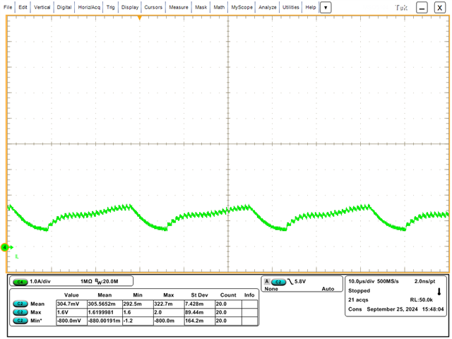
    Also, please see below unstable inductor current waveform in 1.1Mhz, Vin=5.4V and Vout=5.5V and Io=1A.

    The situation also applies to 600kHz because the device triggers its minimum on time.

    Please tell me if you have any questions.

    Best Regards,

    Fergus

  • Hi Fergus-san,

    Thank you for quickly reply, and sharing efficiency data and advice about minimum on time.

    I would like to share these information to the customer.

    And, please let me confirm about my calculation of minimum on time .

    In minimum on duty condition that Vin=5.4, Vout=5.5V, the on duty is 1-(Vin/Vout)=0.018.

    In the case of fsw=600kHz, T=1/fs=1/600k=about 1.67us. Then, minimum on time is 1.67us x 0.018=about 30ns.

    My result is different with yours. Please tell me which process is wrong in above calculation.

    However, I agree that in this use condition, output voltage is unstable, because this device's minimum on time is typ 130ns. Our result shows not enough on time.

    I'm considering the using Back-boost converter product like TPS63070 to solve above. I would appreciate your opinion.

    Best regards,

    teritama

  • Hi teritama,

    You made the same mistake like I did first time.

    Here we must consider the efficiency(assume is 0.91 as tested) and the duty should be 

    1-(Vin*eff/Vout)=0.116, so the calculated on time is 178ns

    another consideration is the frequency variation, the max frequency is 630kHz,

    and the on time is 170ns.

    The datasheet only has the minimum off time 130ns and for the minimum on time, it is 200ns.

    It is recommended to use TPS61033, it is a low voltage device and COT on time control that will not limit by on time

    Best Regards,

    Fergus

  • Hi fergus-san,

    Thanks. It make sense. I could get same result with you. And sorry I was wrong minimum off and minimum on time.

    About minimum on time, how can we know the value 200ns?

    >It is recommended to use TPS61033, it is a low voltage device and COT on time control that will not limit by on time

    ⇒Thank you for suggest. It seems match the requirements.

    Best regards,

    teritama

  • Hi teritama,

    The tested minimum on time data can be seen in our inner system.

    It is not showed in the datasheet.

    Best Regards,

    Fergus

  • Hi Fergus-san,


    I understood that this device's minimum on time is internal information.

    Thank you for your kindly supports truly.

    Best regards,

    teritama

  • Hi teritama,

    You are welcomed.

    Best Regards,

    Fergus