Other Parts Discussed in Thread: BQ25720
Tool/software:
Hi Team,
we are using BQ25710 charger IC in our custom designed board to charge the 3 cell smart battery (RRC-2040-2). we can able to charge the battery but CHRG_OK pin is always low. please the configuration settings used for communication.
Observation / issues:
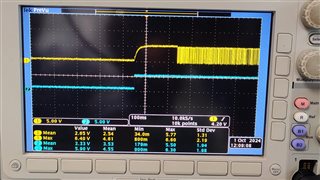
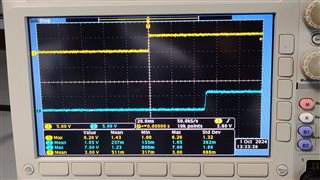
CHRG_OK pin is always low
ADCVSYSVBAT register read value 9 V instead of 12 V
ADCVBUS/PSYS register value VBUS equivalent to 1.9 V instead of 5 V and PSYS is always 0 V
Settings:
Communication: I2C
Device address: 0x09H
VBUS: 5 V
I2C Communication between MCU and Charger IC is working properly and we are able read and write the registers. Please find the register log given below:
| SMBus ADDR | REGISTER NAME | TYPE | DESCRIPTION | SMBUS READING |
| 12H | ChargeOption0() | R/W | Charge Option 0 | 0xE70E |
| 14H | ChargeCurrent() | R/W | 7-bit charge current setting LSB 64 mA, Range 0 mA - 8128 mA |
0x0000 |
| 15H | MaxChargeVoltage() | R/W | 12-bit charge voltage setting LSB 16 mV, Default: 1S-4200mV, 2S-8400mV, 3S-12600mV, 4S-16800mV |
0x3130 |
| 30H | ChargeOption1() | R/W | Charge Option 1 | 0x0211 |
| 31H | ChargeOption2() | R/W | Charge Option 2 | 0x02B7 |
| 32H | ChargeOption3() | R/W | Charge Option 3 | 0X0030 |
| 33H | ProchotOption0() | R/W | PROCHOT Option 0 | 0X4A65 |
| 34H | ProchotOption1() | R/W | PROCHOT Option 1 | 0X81A0 |
| 35H | ADCOption() | R/W | ADC Option | 0X2000 |
| 20H | ChargerStatus() | R | Charger Status | 0X8000 |
| 21H | ProchotStatus() | R | Prochot Status | 0XA800 |
| 22H | IIN_DPM() | R | 7-bit input current limit in use LSB: 50 mA, Range: 50 mA - 6400 mA |
0X4100 |
| 23H | ADCVBUS/PSYS() | R | 8-bit digital output of input voltage, 8-bit digital output of system power PSYS: Full range: 3.06 V, LSB: 12 mV VBUS: Full range: 3.2 V - 19.52 V, LSB 64 mV |
0X1E00 |
| 24H | ADCIBAT() | R | 8-bit digital output of battery charge current, 8-bit digital output of battery discharge current ICHG: Full range 8.128 A, LSB 64 mA IDCHG: Full range: 32.512 A, LSB: 256 mA |
0X0000 |
| 25H | ADCIINCMPIN() | R | 8-bit digital output of input current, 8-bit digital output of CMPIN voltage POR State - IIN: Full range: 12.75 A, LSB 50 mA CMPIN: Full range 3.06 V, LSB: 12 mV |
0X0000 |
| 26H | ADCVSYSVBAT() | R | 8-bit digital output of system voltage, 8-bit digital output of battery voltage VSYS: Full range: 2.88 V - 19.2 V, LSB: 64 mV VBAT: Full range : 2.88 V - 19.2 V, LSB 64 mV |
0X0000 |
| 3BH | OTGVoltage() | R/W | 12-bit OTG voltage setting LSB 8 mV, Range: 3000 mV – 20800 mV |
0X0000 |
| 3CH | OTGCurrent() | R/W | 7-bit OTG output current setting LSB 50 mA, Range: 0 A – 6350 mA |
0X0000 |
| 3DH | InputVoltage() | R/W | 8-bit input voltage setting LSB 64 mV, Range: 3200 mV – 19520 mV |
0X0280 |
| 3EH | MinSystemVoltage() | R/W | 6-Bit minimum system voltage setting LSB: 256 mV, Range: 1024 mV - 16182 mV Default: 1S-3.584V, 2S-6.144V, 3S-9.216V, 4S- 12.288V |
0X2400 |
| 3FH | IIN_HOST() | R/W | 6-bit Input current limit set by host LSB: 50 mA, Range: 50 mA - 6400 mA |
0X4100 |
| FEH | ManufacturerID() | R | Manufacturer ID - 0x0040H | 0X0040 |
| FFH | DeviceID() | R | Device ID | 0X0089 |
Kindly look into this issue and give your feedback as soon as possible.