This thread has been locked.

If you have a related question, please click the "Ask a related question" button in the top right corner. The newly created question will be automatically linked to this question.

BQ51003: FOD Calibration Information and EvKit

Part Number: BQ51003

Tool/software:

Hi,

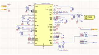
We are using the BQ51003 on two of our new products and we have the same problem on both. I followed the exact same schematic and component values as shown in SLUA748A with component values and coil. We were not able to source the Qi Sniffer from AVID Technologies as it doesn't exist. 

Currently we are finding it very difficult to determine what exactly is wrong with the wireless charging. We are using a WR221230-36M8-G TDK coil as recommended in one of the design notes. We do have a battery sitting right behind the coil but taking it away doesn't make the wireless charging work better. It's basically the same. I started changing the FOD resistor (Changed from 96 Ohms to 440 Ohms). Making it larger does seem to have an effect. But I have no feel for by how much. I have also noted that since doing that, the unit charges very slowly as if only getting a few milliamps from the charger.
We have sources a ST wireless charging TX kit just to get some indication. It is helping me a bit to see what's going on. But at this stage all I can see is that the wireless power terminates sometimes, and I don't know why. I assume the power input (TX power) vs the RX power is too great, and the charger thinks this is due to FOD and then disables or stops the wireless power transmission.
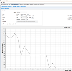
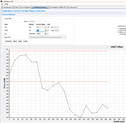
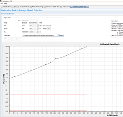
We Seriously need some help. I'm not sure if TI maybe has a better kit than the ST TX as its not of much help. ST also follows a slightly different methodology than TI so it's a bit hard to make out what is what and when. The FOD tool supplied by TI is great, but I can't use it with the ST devkit.
Please let me now if you require more information. We would appreciate any help. It feels like we are close, but after two weeks we are just not getting there. I have one unit that constantly keeps the wireless charging comms going etc. But 3-4 other units that work on and off. I'm not sure what values except for FOD resistor I can change and if I should change it up or down. I have tried to sample some of the ferrite material recommended in another post as we cannot get it easily in South Africa. But I have not heard anything back from Wurth yet and I feel like that is a last resort fix. 
Kind regards.
  • Hello

    Could you send a schematic for review.

    Also a scope capture of the of the RECT pin at startup will help. see attached.

    I am looking for what is failing in the startup sequence.

    0116.TX Start up and Comm Packets Guide.pdf

  • Hi Bill,

    Sorry for the delay. As things happen, we got two units to work more consistently. The 440 Ohm resistor for FOD resistor seems to work. We don't have startup failures, so I have not done any scope captures of the startup sequence. We actually have a problem where I'm not able to calibrate the FOD resistor as I have no feeling for what an acceptable value is or isn't.  Also, I have no way to measure the current on the TX I can maybe only measure the RX current.

    But the main problem is that it's charging very slow (maybe this is expected) and sometimes the charge terminates so it seems like the device (RX coil) has to be exactly center aligned with the TX coil. I would have hoped for some play (maybe 5 mm in each direction) that would still allow power transfer. 

    But mainly we need to do FOD tuning, and I need to get it to work consistently. Feels like we are there. Im not sure if 440ohm is acceptable or should I also adjust the current limit resistor?

    See the schematic below

  • Hello 

    440 ohms for Rfod (R18) is much larger than typical.  Current limit is set by R17 and R18, only increasing R18 will reduce current limit.  When R18 was increased was R17 decreased to keep current limit at the same point?

    But the main problem is that it's charging very slow (maybe this is expected) and sometimes the charge terminates

    What can you tell me about the battery charge IC?

    The current at OUT can be measured / monitored at ISET Pin.  Ratio is about 262 to 1.

  • Hi Bill,

    Sorry for the late reply. We are using a PMIC from Analog - MAX77658AANX+T. We are using the MAX77658 to do the battery charging, coulomb counting and as power passthrough when powered via the wireless charger. The output of the wireless charger is the input to the PMIC. The schematic is attached as an image. I have also added a screen capture off the HW setup. The charging coil is at the bottom, closest to the charger (TX). The battery is then right above the coil and the PCB on top of the battery. I'm sure this will affect FOD but there is no other way for us to do this. It's a wearable tracking device. 

    I will check the current in and out. Oh, and no I have not adjusted any of the other resistors. I just fiddled with R18 (Rfod) to get it working stable and 440 ohms seems to be the magic value at this stage. I'll check on a used battery to see what the current is like when I put it onto the charger just now and will report back as soon as possible. 

    Thank you for the support.

  • Thanks for the additional information. 

    AC field from the TX will enter battery and probably heat it up, in addition to causing FOD issues.

    Recommend trying a magnetic shielding material behind the RX coil to prevent AC field from entering battery and PCB.

    We have used Wurth 354002  

  • Thank you, Bill. We have placed an order for the magnetic shielding. It will take some time to get to us. Will test it as soon as possible. I hope that this will improve the FOD situation. 

    Bill you previously said we can measure ISET to determine the current being drawn on the Output and that it's a 262 to 1 ratio. I measured 1.159V on ISET. This gives me a 4.423mA.

    The battery and PCB get very warm as you have stated above. I assume all the energy is lost into the battery. I think the shield is going to help out a lot here.

  • Hi we finally got the shielding. It seems to help out quite a bit as the battery doesn't get as hot as before. The FW guy also found a bug in the code that would allow the battery to be charged at a higher charge current than it should be. So, we lowered that and that also helps out quite a bit. I was also able in the meantime to get the ST TX Devkit to stop from shutting down when a large power loss is detected due to FOD. This also helps me a lot to then be able to tune the values.

    I'm going to prepare everything today to start with proper tuning as it now feels like I have the tools to help me out and don't have to keep guessing values until it works. I'll give feedback as soon as possible. Two of my PCBs are working on a commercial wireless charger just by adding the magnetic shield material. Two of my other PCBs for a different product doesn't even with the magnetic material. I'm going to try and tune those first.

    Thank you for the help so far.

  • Good to hear it is working, let me know what the test results look like.

  • Hi Bill,

    I have done some tuning. After feeling quite confident that I was doing things right. I got to the point of measuring VRECT and this is where things started looking bad (maybe I don't know). The reason I say this is because my waveform doesn't look like the example waveforms. It might be my oscilloscope (very old Tektronix TDS 1012 100MHz 1GS/s). If you look at the example waveform in the user guide, I'm also confused as to where exactly I need to measure VRECT. It is showing two places. So, which one is the one I note in the table then? It seems to be the second one. I have included my captures too. I used the base of the waveform for my values in the table. Note the waveform I'm showing does have the Ros resistor fitted (20k) this was after tuning. Except form voltage differences my waveforms look the same before and after tuning.

    Example from SLUA731

    My captures:

    I did remove the GND lead of the probe and used a spring lead to get really close to see if the waveform looks different. But it looked the same, maybe clearer.

    I have attached my values pre_tuning and post_tuning. I had a problem tuning the VOS voltage as my locale didn't allow me to change the values at the time. I have in the meantime also fixed that from "," to a ".". I anyways just stayed with the 10mV default from the FOD GUI program. 

    after tuning using RFOD = 285 ohms and Ros = 20k I got this below. A lot better than I had initially but still off by quite a bit.

    My assumption is I'm not measuring VFOD correct. Also setting VOS would maybe have made a big difference. I want to re-do the test. But I'll rather wait for your feedback. 

    We have a 250mAh lipo battery that can be charged at 0.5C so 125mA. Although I did set the current limit to 557mA (RIlim = 470ohm) I was not able to go above 450mA before the supply would drop out.

    VRECT (V)	ILOAD (mA)	VOUT (V)	PPT (mW)	PPR    (mW)	VFOD (mV)
    7.22	0.00	5.00	650	0	1.00
    7.08	25.00	4.99	894	117	18.86
    6.36	50.00	4.99	1002	273	36.50
    5.63	75.00	4.98	1045	390	54.50
    5.61	100.00	4.98	1235	585	71.90
    5.58	125.00	4.98	1430	742	89.80
    5.58	150.00	4.97	1454	820	107.60
    5.13	175.00	4.97	1478	937	125.00
    5.10	200.00	4.96	1665	1093	143.20
    5.10	225.00	4.96	1920	1250	161.00
    5.10	250.00	4.95	2060	1406	178.90
    5.08	275.00	4.95	2175	1601	206.30
    5.08	300.00	4.95	2373	1757	224.60
    5.06	325.00	4.94	2552	1875	243.40
    5.06	350.00	4.94	2825	2109	262.00
    5.06	375.00	4.94	3010	2265	279.20
    5.06	400.00	4.93	3250	2421	299.10
    5.06	425.00	4.93	3536	2578	317.30
    5.08	450.00	4.92	3784	2734	336.10

    VRECT (V) ILOAD (mA) VOUT (V) PPT (mW) PPR (mW) VFOD (mV)
    7.22 0.00 5.00 650 0 1.00
    7.08 25.00 4.99 894 117 18.86
    6.36 50.00 4.99 1002 273 36.50
    5.63 75.00 4.98 1045 390 54.50
    5.61 100.00 4.98 1235 585 71.90
    5.58 125.00 4.98 1430 742 89.80
    5.58 150.00 4.97 1454 820 107.60
    5.13 175.00 4.97 1478 937 125.00
    5.10 200.00 4.96 1665 1093 143.20
    5.10 225.00 4.96 1920 1250 161.00
    5.10 250.00 4.95 2060 1406 178.90
    5.08 275.00 4.95 2175 1601 206.30
    5.08 300.00 4.95 2373 1757 224.60
    5.06 325.00 4.94 2552 1875 243.40
    5.06 350.00 4.94 2825 2109 262.00
    5.06 375.00 4.94 3010 2265 279.20
    5.06 400.00 4.93 3250 2421 299.10
    5.06 425.00 4.93 3536 2578 317.30
    5.08 450.00 4.92 3784 2734 336.10

    VRECT (V)	ILOAD (mA)	VOUT (V)	PPT (mW)	PPR    (mW)	VFOD (mV)
    6.32	0.00	5.00	508.00	820.00	93.00
    6.25	25.00	4.99	725.00	1015.00	118.60
    5.56	50.00	4.99	820.00	1093.00	134.50
    5.49	75.00	4.98	1002.00	1328.00	159.60
    5.49	100.00	4.98	1193.00	1562.00	185.50
    5.10	125.00	4.97	1158.00	1523.00	206.50
    5.10	150.00	4.97	1331.00	1757.00	232.80
    5.08	175.00	4.96	1564.00	1953.00	258.30
    5.06	200.00	4.96	1683.00	2187.00	284.50
    5.08	225.00	4.95	2046.00	2656.00	336.60
    5.08	250.00	4.95	1969.00	2734.00	348.00
    5.08	275.00	4.94	2177.00	3007.00	374.30
    5.08	300.00	4.94	2364.00	3203.00	401.00
    5.06	325.00	4.94	2605.00	3515.00	427.60
    5.06	350.00	4.93	2799.00	3789.00	454.50
    5.04	375.00	4.93	3040.00	3984.00	480.50
    

    VRECT (V) ILOAD (mA) VOUT (V) PPT (mW) PPR (mW) VFOD (mV)
    6.32 0.00 5.00 508.00 820.00 93.00
    6.25 25.00 4.99 725.00 1015.00 118.60
    5.56 50.00 4.99 820.00 1093.00 134.50
    5.49 75.00 4.98 1002.00 1328.00 159.60
    5.49 100.00 4.98 1193.00 1562.00 185.50
    5.10 125.00 4.97 1158.00 1523.00 206.50
    5.10 150.00 4.97 1331.00 1757.00 232.80
    5.08 175.00 4.96 1564.00 1953.00 258.30
    5.06 200.00 4.96 1683.00 2187.00 284.50
    5.08 225.00 4.95 2046.00 2656.00 336.60
    5.08 250.00 4.95 1969.00 2734.00 348.00
    5.08 275.00 4.94 2177.00 3007.00 374.30
    5.08 300.00 4.94 2364.00 3203.00 401.00
    5.06 325.00 4.94 2605.00 3515.00 427.60
    5.06 350.00 4.93 2799.00 3789.00 454.50
    5.04 375.00 4.93 3040.00 3984.00 480.50

    Kind regards,

    Quintin van Wyngaardt

  • Hi Bill,

    I tried doing the "tuning" a bit different. Since I have a precision potentiometer connected, I just adjusted RFOD till the TX and RX power was almost on top off each other. I then tested the complete range again and the TX and RX power stayed within 100mW of each other up to 400mA load. Also, in the process I realised I'm being daft. The reason the current was dropping off at 400mA is because it's a 2W rx coil. 

    Is the method I'm using acceptable? I'm still using Ros of 20k and my RFOD ended up being 221 Ohm. I'll set it to 220 as its a standard value and make sure things are still working fine.

  • Hello

    Thanks for update.

    If you can read TX and RX power, then you can calculate loss. The target loss would be -25mw to -350mW across the load range.  RX power needs to be greater than TX power.  This would be the alternate tuning you used.  

    The Potentiometer can be used, but a caution -- the ground for them should be directly to PCB near IC and separate from the power gnd.

    Ros -- will help loss at low load 0mA to ~ 25mA.

    Rfod -- above that point.

  • Hi Bill,

    Thank you for the support. Just to maybe help others I'll summarize what I had to do to get to this point. According to me I'm now able to tune my circuit successfully and have tested it on a few different wireless chargers and it seems to be working fine. Looking at the loss figures I was able to get both our products to stay within the -25mW to -350mW range.

    Summary:

    1. Had to obtain a STEVAL-WBC86TX kit via Mouser as ST for some reason stopped supplying it themselves. Oh, and the Qi Sniffer recommended by TI from AVID Technologies is also not available anymore.

    2. I had to special request the GUI software for the STEVAL-WBC86TX kit from ST.

    3. I did use the TI FOD Calibration software, but I did not get nice results from that as the document describing the process lacks describing where to exactly measure the Vrect Value from the oscilloscope capture.

    4. I decided to go with the manual method of tuning. I put back the default Ros resistor of 20k and setting the current limit resistor to enable max current, as described in the TI FOD documentation. I then connected a precision pot in place of RFOD and set it to default of 196 ohm. I then watched the RX and TX power on the STEVAL kit and tuned the RFOD value until the RX power was a bit more than the TX power. I then adjusted the load from 0 - 400mA (my max) and made sure that the RX power stayed above the TX power and that Ploss (Ptx - Prx) was within the specified limits (-25mW to -350mW). I also measured Vout just to make sure it is above 4.8V to 5V at the various loads.

    5. We added the Wurth 354002 ferrite material between our battery/pcb and the RX coil. This helped the battery and PCB not to get as hot and improved the efficiency.

    I consider this case closed. I'm marking this as issue resolved. Thank you for the help and guidance.