This thread has been locked.

If you have a related question, please click the "Ask a related question" button in the top right corner. The newly created question will be automatically linked to this question.

UCC28780: (another) startup issue

Part Number: UCC28780

Tool/software:

Hello!

I have designed an off-line AC-DC converter, 85-253Vac universal input, 26V/3A output, based on UCC28780 and built some working prototypes. So far, so good!

I was working on one of these prototypes, trying to optimize the feedback compensation network, when it suddenly stop working.

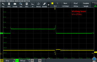
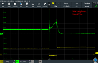
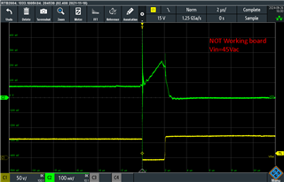
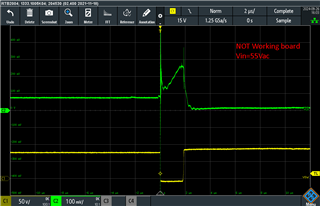
Now, with no load, when I slowly increase the input voltage, I can see only one 2us pulse on PWML, up to about 50Vac input. With this input, the voltage on the Rcs sense resistor reaches only about 210mV.

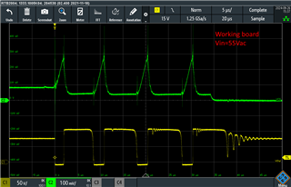
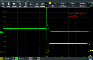
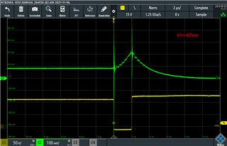
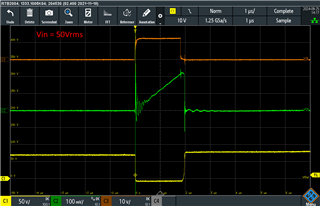
   C1: QL Drain, C2: Vcs, C3: QL Gate

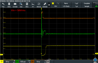
If I raise again the input voltage, when it reaches about 58Vac the PWML pulse reduces to less than 1us and stay there even with higher input voltage:

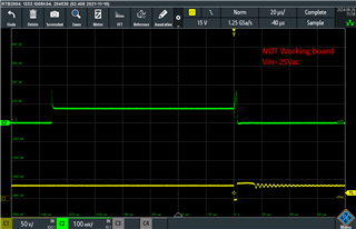
What can cause this behavior? I repeat: the converter was working properly before I did something (what?) that broke it.

I already replaced the UCC28780 and double checked the transformer, with no result... I was trying different values for the compensation network, but I don't think that this can be the cause.

Thank you very much in advance.

Best regards,

Sergio

  • Hello, many thanks for your prompt reply.

    I have already read the document but it is not helpful in this case. As I wrote, my design is almost ready for production and I have many working samples.

    The behavior I see in this particular prototype is not documented in the datasheet or appnotes.

    I'm just wondering what it could be due to in your opinion, because I haven't been able to repair this board yet.

    Thank you very much again.

    Best regards,

    Sergio

  • Hi,

    That document has a section for PWML shows 1 pulse only. It looks there is some short or open. Note the IC solder is quite delicate. 

    The table 3 lists all we know why PWML only shows 1 pulse. 

  • Hi,

    already checked for short or open pins, all is ok. I replaced the UCC28780 with a new one, nothing changed.

    My question is: why the first PWML pulse width reduces from 2us to about 400ns when the input voltage is greater then 50Vac?

    Instead, it should remain at 2us in order to allow the Vcs to reach the threshold voltage of 280mV...

    Regards,

    Sergio

  • Hi,

    It looks the IC detects the CS peak already over its threshold - so it looks there is noise. Can you compare this to a good board to see if your oscilloscope with full bandwidth?

  • Hi Hong,

    here is some measurements done on a working board:


    And these are the same measurements taken on the broken board:


    All measurements show the voltage at the switching node and the voltage right at the CS pin of UCC2780, all made with the full bandwidth of a 300MHz oscilloscope.

    I checked everything many times and seems all ok, I am going crazy...

    Many thanks again, best regards

    Sergio

  • Hi Sergio,

    I think during startup the IC verifies if the CS pin signal is ok during first few pulses (2/3) and again verifies if the voltage is above brown in threshold. If all these conditions are met, then IC will try starting up. If there is sufficient noise at CS pin, it will lead to narrowing of PWML pulses preventing startup. I would sugest increasing the capacitance here/ placing this close to IC pin and GND to see if this helps startup.

    Regards,

    Harish

  • Hi Harish,

    sorry for late reply, last friday I worked from home...

    As you suggest, today I tried different values for capacitor Ccs, up to 470pF, with the same Ropp=4k22. Something changes, but still the converter does not start.

    With 470pF, the width of the first (and unique) PWML pulse sticks at 2us even at 80Vac input, but now the voltage at CS pin is lower and doesn't reach the 280mV level. Other boards starts switching in SBP mode at about 78Vac, with Ccs=33pF and Ropp=4k22. 

    Here are the waveforms at 80Vac input:

    Best regards,

    Sergio

  • Hi Sergio,

    Can you please share the copy of your excel calculator?

    It looks like there is an issue with CS pin which is preventing this startup.

    Regards,

    Harish

  • Hello Harish,

    sure, here it is:

    UCC28780 Excel Design Calculator (Rev. D) SLUC664D - RevL Trafo_Definitivo_2.xlsx

    As I already wrote, other prototypes based on this calculation work properly (with Ccs=33pF instead of 10pF).

    Thanks again!

    Best regards,

    Sergio

  • Hi Sergio,

    Thank you for sending the calculations. It looks fine.

    Have you tried swapping the controller from the non functional board with the other boards which are working? This might rule out controller and other things around it will need to be check.

    Regards,

    Harish

  • Hello Harish,

    thank you for reviewing my calculation sheet.

    Unfortunately, I don't have the right tools to unsolder the controller without risk of breaking it, so I tried to replace (for the second time) the UCC28780 with another one, of course taken from the same reel.

    The result is the same, only one PWML pulse, even at input voltage well over the brown-in level.

    I've checked everything several times and everything seems ok, so the controller seems to be the culprit, but replacing it twice didn't help.

    At this point, I don't know what to do anymore...

    Thank you so much anyway!

    Best regards,

    Sergio

  • Hi Sergio,

    Thank you for the feedback.

    I think we might one more experiment where we will need to put the IC from the same reel into one of the working boards which you have. This will confirm if the issue is with the controller lot or the board. Can you please check that for us?

    Regards,

    Harish

  • Hi Harish,

    I did the experiment you suggested and (of course...) the working board still works after replacing the controller...

    So I started to desolder and measure every single resistor and capacitor connected to the controller on the broken board.

    This way I finally found the culprit: I found the Rvs1 resistor completely open!!

    Replaced it with a new 43k2 resistor and now the board is working again!

    At this point, I have a doubt. As I wrote in my first post, the board was working when it suddenly stopped switching.

    Why did Rvs1 break down? It's a common 0603 thick film resistor (Yageo RC0603FR), is such a resistor suitable in that position? 

    Its datasheet states a maximum overload voltage of 150V, but only 75V of maximum working voltage:

    At 254Vac input, the voltage at Vaux node should reach about -60V, but maybe can exceed 75V if there is some ringing: is a higher voltage rated resistor needed in this position?

    Also on the demo board UCC28780EVM-021, a 0603 resistor (R29, same type Yageo RC0603FR) is used in the same position.

    Thank you very much again for your support!

    Best regards,

    Sergio

  • Hi Sergio

    Good to know the problem is identified.

    I think you are correct Rvs1 could breakdown due to the voltage here: max input voltage and turn ratio. I will mark this as resolved for now.

    Regards,

    Harish