This thread has been locked.

If you have a related question, please click the "Ask a related question" button in the top right corner. The newly created question will be automatically linked to this question.

LM5041B: LM5041B related issues

Part Number: LM5041B

Tool/software:

Hello,

Question1:The customer uses LM5041B for DCDC module power supply, with an input voltage of 48V, output voltage of 28V, power of 500W. When the capacitive load value is large, it is about 5000uF. When the module is powered off, the output side voltage will reverse. How can I solve this problem?

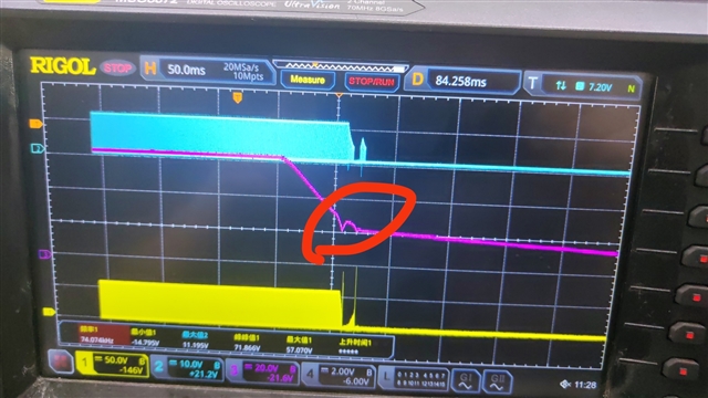
As shown in the waveform below:

The yellow line represents the VDS of the output rectifier, the blue line represents VGS, and the purple line represents VIN voltage

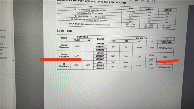
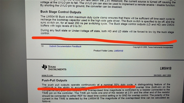
Question2:Is there a problem with the underlined description as shown below;

Thanks!

  • Hi Jeno, I have some follow up questions for this

    -Firstly, could you please share Schematic for a better debug? Once the schematic is provided, please point out the Output rectifier which Vds and Vgs voltages are shown in the waveforms above. Also, please point out the capacitive load, I guess this the output capacitor in your schematic.

    -Secondly, could you please explain what you mean when saying the "output voltage is reversed". Could you please provide waveforms?

    -Thirdly, how are you supplying VIN voltage to the device? Are you using a power supply? According to your waveforms VIN is ramping down which will make UVLO pin to go down to 2.5V threshold and then the device will stop switching (as shown in your waveforms).

    -Finally, regarding description mentioned in the DS, it is explaining that LD, HD, PUSH and PULL pins will be low if UVLO is triggered at UVLO pin (2.5V).

    Thank you