This thread has been locked.

If you have a related question, please click the "Ask a related question" button in the top right corner. The newly created question will be automatically linked to this question.

BQ27Z746: Query on learning cycle and chemical ID identification of LiPo battery

Part Number: BQ27Z746
Other Parts Discussed in Thread: BQSTUDIO, , BQ25628E, GPCRB

Tool/software:

Hi Team,

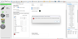
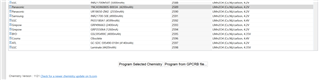
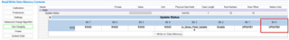
In our project, we are using a LiPo battery, and we need to identify its chemical ID. We are using the BQ27Z746 fuel gauge for monitoring the battery parameters through BQStudio and the BQ25628E as the battery charger. We have attempted to calibrate the fuel gauge using BQStudio and successfully calibrated the cell voltage with the measured cell value. However, we were unable to calibrate the other values according to the hardware design parameters. To identify the chemical ID, we referred to the TI document 'Simple Guide to Chemical ID Selection Tool (GPC) (Rev. A)' and having some doubts in the process ,its mentioned below .Please help us to solve this. 

Q1. How is the relaxation mode conducted? Was the battery in connection with the fuel gauge during this mode or else disconnected from the fuel gauge and relaxed for 2 hours.
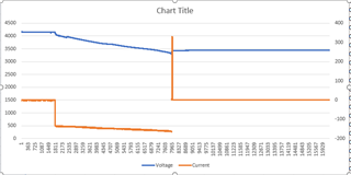
Q2.During the charging mode, we set the power supply to 350 mA, and the board drew a charging current of 260 mA with the load turned off. Could you please confirm which current value should be used for calibration in  BQStudio? Additionally, during the discharging mode, we discharged the board with a load of 350 mA while ensuring that the charger was not connected.
Q3. Is it necessary to calibrate in each mode of operation after it has been calibrated in charging mode?
Q4. Could you please provide the values for the parameters listed below? We have attempted to configure them using the default values as listed below, but we have not been successful.
OVP 4100 mV
UVP 3300 mV
OCC 14 mV
OCD -16 mV
SCD -20 mV
I-Wake -2 mV
BDP -200 mV
BCP 200 mV
BDN -200 mV
BCN 200 mV

Regards,

Nithya

  • Hello Nithya,

    1.) The gauge should always be connected to the battery. Relaxation is just a period of time where there is 0 current flowing through the battery. Just ensure there is not a discharge or charge current being applied to the battery.

    2.) Please do calibration with a discharge current of 1 amp. Ensure that 1 amp of discharge current is applied and do calibration.

    3.) Calibration only needs to be done once.

    4.) These values are defined by you the user. In terms of how to calibrate protection I would reference section 6 of this document: https://www.ti.com/lit/ug/sluuch4a/sluuch4a.pdf

    Regards,

    Adrian

  • Hi Adrian,

    We successfully calibrated the fuel gauge at a battery voltage of 3623 mV. However, when we attempted to update the OVP and UVP values to 4100 mV and 3300 mV, respectively, an autotrim failure occurred for the OVP. Currently, the charging toggles every second during the recovery time.

    Could you please help us resolve this issue as soon as possible? We are in a critical situation, as the board needs to be delivered to the customer within four days following this learning cycle process.

  • Hello Gopika,

    To use the Protector Threshold tab, the voltage applied to the gauge must be a close match to the number it's being set to. It seems you have a battery connected to the gauge. Therefore, I would recommend using the "Protector Tuning" tab as this does not need a reference voltage.

    Regards,

    Adrian

  • Hi Adrian,

    Please let me know what is meant by the Applied pack voltage specified in the calibration field?

  • Hello Gopika,

    That is the voltage that is seen on the PACK pin. I would recommend using a Digital Multimeter to measure the voltage on the PACK pin.

    Regards,

    Adrian

  • Hi Adrian,

    We have completed the process for the chemical ID and have received the log file. However, the GPC tool is continuously sending error messages while uploading the extracted file. Kindly verify the attached files and provide us with feedback.

    3443.GPC_ChemID_Data.zip

  • Hello Gopika,

    This is what the voltage and current graph First, there should be a constant current discharge, as you can see the current slowly start to increase as the discharge goes on. Also, at the end of discharge there is just weird charge pulse that occurs that should not happen.

    Regards,

    Adrian

  • Hi Adrian,

    We have received the chemical ID 2589. However, this ID is not available in the battery chemistry options for programming via "Program Selected Chemistry." Therefore, we plan to program the chemical ID using the GPCRB file.

    Could you please clarify what this file is and where I can obtain it? I’ve attached the files we received after submitting the log file from the REL-DIS-REL process for your reference.

    Additionally, could you specify whether the battery needs to be fully charged at the initial state of the learning cycle, specifically during the initial discharging cycle?

    We also attempted to change the update status to 00 by enabling the gauge and resetting it via toggling. Unfortunately, the update status is currently showing 01. Could you provide guidance on this as well?

    Chemid-2-report.zip

  • Hello Gopika,

    I can see the ChemID 2589 on my side. Make sure you update the chemistry version for BQStudio. https://www.ti.com/tool/GASGAUGECHEM-SW

    The battery can be in any state for the initial discharge, does not need to be fully charged.

    What command did you use to enable the gauge?

    Regards,

    Adrian

  • Hi Adrian,

    We programmed the ChemID using 'Check for a newer chemistry update on ti.com' and now its fine. We toggled the 'GAUGE_EN ' in the 'Commands' bar (On the right side of BQStudio ) and enabled the GAUGE_EN bit in the Manufacturing status register, but the Update status 01.Please help us to resolve this at soon as possible because we need to complete the learning cycle on high priority.

    Best Regards,

    Nithya

  • Hello Nithya,

    Can you send me a log file from the gauge of you sending the "GAUGE_EN" command. Can you also send me the gg file from the gauge before and after sending the "GAUGE_EN" command.

    Regards,

    Adrian

  • Hi Adrian,

    Attached is the log file showing the start of the learning cycle process. The log begins with the 'GAUGE_EN' command, followed by a complete battery discharge to empty, a 14-hour and 36-minute relaxation period, and charging the battery to 4.17V(Dis-Relax-Charge).We will send the gg files as soon as possible.

    log file.zip

  • Hi Adrian,

    Please find the attached .gg file showing the gauge status before and after executing the 'GAUGE_EN' command. We tried multiple times to update the 'update status' in Gas gauging according to the guidelines outlined in the Achieving the Successful Learning Cycle document, but it didn't work properly as expected .

    We would appreciate your prompt assistance in resolving this issue, as this task is a high priority for us.

    We are also attaching a document detailing the procedure we followed for identifying the ChemID and completing the learning cycle . Kindly review it and help us to resolve the issue.

    gg_file_and_process_flow_doc.zip

    Best regards,

    Nithya

  • Hello Nithya,

    I see what happened now, for some reason bit 0 of the update status register was already set to begin the test. I would recommend restarting the learning cycle process. Before you restart, make sure to change bit 0 back to 0 (green). Update status can be found in the gas gauging section of data memory.

    Regards,

    Adrian

  • Hi Adrian,

    We attempted to update the 'update status' bit by toggling bit 0, and it is now in a low state. Following this, we restarted the learning cycle process. However, after completing the full charge and entering the relaxation phase, the QMAX bit in the IT status is not updating to high as expected.

    At this point:

    • VOK and RDIS are both in low state.
    • REST bit is in  high state.

    We have attached the log file for your reference. Please assist us in resolving this issue.

    4111.log_file.zip

  • Hi Adrian,

    We have completed the learning cycle as outlined in the documents "Achieving The Successful Learning Cycle" and "Simple Guide to Chemical ID Selection Tool (GPC)" from TI. This process took three days to finalize.

    Initially, we conducted the chemical ID test. Subsequently, the gauge was programmed with the obtained chemical ID 2589, and we completed the learning cycle. The steps involved in this process are detailed in the attached document, along with notes on results that did not meet our expectations.

    Could you please advise on how we can ensure the accuracy of the golden image obtained from this process? PFA the srec file with this reply.

    ChemID_and_Learning_Cycle_Procedure_for_BQ27Z746_REVB_14OCT2024.pdf

    ChemID_Data.zip

  • Hello Gopika and Nithya,

    I looked over the log file and see something very concerning.

    As you can see, the voltage rapidly jumps about 300 mV without a change in current. This is mostly the cause of why the learning cycle is failing to complete. Battery voltage should not be jumping like this

    Regards,

    Adrian

  • Hi Adrian ,

    The charging process completed without any physical disturbances in the surroundings, but we will check this . If possible, could you suggest why this behavior might be occurring?

    Regarding the learning cycle, we reconfigured some threshold values (e.g., UVP, OVP) in the golden image obtained from the previous learning cycle. We need a new golden image. Could you please confirm whether we need to restart the learning cycle with the new configuration, or if it’s sufficient to take the new golden image directly from the 'Golden image' menu after reconfiguration?

    Regards,

    Nithya

  • Hello Nithya,

    I am not familiar with a voltage jump like this without a rapid change in current. There must be something external that is affect the voltage reading.

    If you are making changes to protection settings, you do not need to run the learning cycle again after completing it.

    Regards,

    Adrian

  • Hi Adrian,


    We used the fuel gauge BQ27Z746YAHR and performed learning cycle again to generate the golden image. But during the process we didn't get some of the bits  correctly as mentioned in the reference document of TI for performing learning cycle. 

    Initially we set the Update status to "00" and after toggling the GAUGE_EN command in BQ-Studio the Update Status changed to "04".

    After that we started discharging and completed the next relaxation, including initial charging. Until this the bits are changed as per the expectation.

    But during the relaxation after charging, the Update Status didn't changed to "05" and QMAX bit didn't toggled to indicate QMAX update. 

    In order to proceed further, we manually edited the Update status to "05". Then continued with discharging of the fully charged battery(4.1V Lipo battery).

    After completing the discharging we started the relaxation state. But the REST bit didn't get high even after we waited for more than 10 Hours. The update status was supposed to be "06" or "0E" by this time. As this doesn't happened, we manually wrote the Update Status to "06" and waited few hours to check whether will it be get automatically updated to "0E". But this also didn't worked. So, we performed one more Charge-Relaxation-Discharge cycle as mentioned in the reference document. But that also didn't give any expected results.

    So after keeping the battery in 1 hour relaxation we manually edited the Update status to "0E". We kept the battery in that state for half an hour and completed the learning cycle by generating the Golden Image.

    Could you please help us to identify why we didn't get the proper bit updates in BQ-Studio and to find out if there are any errors happened during the process?

    Please note that the discharging is started at 300mA load current for fully charged battery. Later this load current is reduced to 20mA at 3.2V as the battery should be discharged to the termination voltage (3140mV) and the low battery voltage was not able to drive higher load. Do the above mentioned method is correct for discharging or can you please let us know which is the correct method for discharging?

    Please find the attached Log file generated during the entire learning cycle and gg file generated after completing the learning cycle for reference

    The Chem ID used in the process is : 3759

    Battery Details : 3.7V, 1500mAh, Li-Po Battery

    The reference document used is : SLU903 ( Achieving the Successful Learning Cycle ) by TI.

    0333.FUEL_GAUGE_LEARNING_CYCLE_01NOV2024.gg.csv

    0333.LOG_FILE.zip

  • Hello Gopika,

    Thank you for the data, give me some time to look through the data and root cause your issue.

    Regards,

    Adrian

  • Hello Gopika,

    Please do not manually change the update status register, this should update automatically. I will need you to manually change update status back to 0x04. Can you reattempt the learning cycling but this time discharge all the way down to 2.5V and make sure to relax for 5 hours. Then charge to all the way up to 4.2V.

    Regards,

    Adrian

  • Hello Adrain,

    We waited hours to change the update status automatically. Unfortunately this doesn't happened. Currently we have discharged the battery to 3140mV. Now  as per your suggestion we need to discharge the battery to 2.5V so we have to remove the BMS protections. But as per the datasheet of LiPo battery used the discharge cut off voltage is 2.75V. Can this been done? Please comment. Hereby attaching the datasheet of battery with this.

    7215.SDS 503450.pdf

  • Hello Gopika,

    Yes, only discharge down to 2.75V.

    Regards,

    Adrian

  • Hi Adrian,

    We have some queries regarding the updating of data memory related to the 'term voltage' which is explained below . Could you please provide clarification on this, 


    1. If set the term voltage to 2750mV as suggested , there are chances that the battery voltage will directly drop to 0V before reaching to the term voltage and the fuel gauge will not detect the battery after that for further steps. Because in earlier ,when we fully discharged  the battery individually with an electonic load having constant load current of 300mA ,  observed that battery voltage dropped to 0V when reaching 2.953V at battery voltage ,but the expected cut-off voltage was 2.75V according to the discharging rate mentioned in the data sheet.

    2. If  reducing the discharging current after the battery voltage reaches 3.3V and expected that the the cut-off of the battery might occur slightly below 2.953V.
    So can we proceeds to update the data memory using the below values? is it okay to set the Term voltage as 2.9V?


    Termination voltage : 2900mV
    CUV : 2850mV
    UVP : 2870mV
    UVP Recovery : 2880mV
    CUV Recovery : 2860mV
    FD Set threshold : 2910mV

    Please help us to provide clarity on this.

    Regards,

    Nithya

  • Hello Nithya,

    This should hopefully be fine. We will see if this allows the update status to change to 0x05. Please start another learning cycle attempt with these settings.

    Regards,

    Adrian

  • Hi Adrian ,

    Thank you! We'll perform the learning cycle and update you with the results as soon as possible.

    Regards

    Nithya

  • Sounds good, I will be awaiting to hear from you.

    Regards,

    Adrian

  • Hi Adrian,

    We began the learning cycle by updating the data memory values as previously discussed, setting the term voltage to 2900mV. Initial discharging began with a constant load current of 300mA. At around 3.2V, we reduced the load current to 150mA and continued discharging. When BQStudio detected a voltage of 2953mV, the battery voltage drained to 0V. so we were unable to drain the battery voltage down to the term voltage.

    Can we able to decrease the load current below 150mA for discharging ? or need to use constant discharging current during entire process?

    In the reference document, it is stated that the final discharging current can be as low as C/10 but in the initial discharging not specified about load current. For our battery, C is 1500 mAh. However, in terms of new term voltage value, we cannot discharge to meet the term voltage because this would drain the battery to 0V.

    Please specify about the discharging load current in detail way in both initial and final discharging steps

    Please provide clarity on this ,your support on this would be appreciated.

    Regards,

    Nithya

  • Hello Nithya,

    You will need to use a constant current when discharging. I would recommend using a rate of C/7 and don't step down this current. Discharge down close to the point where any protections will trip.

    Regards,

    Adrian

  • Hi Adrian,

    Good news ! 

    Thankyou for your support.

    We reattempted the learning cycle with a constant load current of 150 mA during discharge . Currently, the process is progressing as expected, with the update status bit now showing 05. Currently second discharging is ongoing.

    However, we have a concern regarding the golden image exporting  process. In the reference document, we noticed a sentence in the conclusion page which shown below, we need to do this before exporting the golden image file? Please provide clarity on this.

  • Hello,

    The team is currently out of office today. We will get back to you next week.

    Regards,

    BMS Apps Team

  • Hi Adrian,

    Thank you for the information. 


    We have a Good news, and thank you for your continued support!  

    During the final relaxation stage of the learning cycle, we observed the Update Status bit transition from 05 to 06. However, it did not change from 06 to 0E in the final relaxation.  

    As per the reference document, we are now performing another Charge-Relaxation-Discharge cycle. During the relaxation phase after charging, we were able to observe the Update Status change from 06 to 0E. The remaining discharging cycle still needs to be completed.

    That said, we have a few concerns regarding the next steps in the learning cycle, and we would appreciate your guidance on the following:

    • Is it acceptable to take the golden image during the relaxation phase after charging (since the Update Status is 0E), or should we complete the discharging phase, as mentioned in the reference document, before capturing the golden image?  

    • If discharging is necessary, can we take the golden image immediately after the discharging phase, or should we wait for the REST bit to go HIGH to ensure proper relaxation?  


    • The reference document states that before saving the golden image, we must set the Update Status to 02 to disable IT gauging, reset the Qmax Cycle Count to 0, and set the Cycle Count to 0. Is this step required, or can we proceed with taking the golden image once the Update Status is 0E?  


    We would greatly appreciate your insights and suggestions on these points.  

    Regards,

    Devika 

  • Hello Devika,

    This is great news to hear! Since Update Status is 0x0E it is completely acceptable to take the golden image file from the gauge, you do not need to complete the discharge phase. It is necessary to reset the Qmax cycle count to 0 and the cycle count to 0. However you can keep update status to 0x0E. 

    Regards,

    Adrian

  • Hi Adrian,

    Thank you for the information.

    As discussed, since we have not observed the transition of the Update Status from 06 to 0E, we conducted another Charging - Relaxation - Discharge cycle as described in the reference document. Due to uncertainty about when to generate the golden image, we created three different golden image files throughout the process after getting the Update status to 0E , as outlined below:

    1. The first golden image was generated when the Update Status changed to 0E during the relaxation phase after charging, without altering the Update Status, QMAX Cycle Count, or Cycle Count. At that time, the values were 0E, 2, and 2, respectively.

    2. The second golden image was generated after completing the final discharge in the Charge - Relaxation - Discharge process, as outlined in the reference document, without changing the Update Status, QMAX Cycle Count, or Cycle Count. The values remained 0E, 2, and 2, respectively.

    3. The third golden image was generated after completing the final discharge, but this time, we updated the Update Status, QMAX Cycle Count, and Cycle Count to 02, 0, and 0, respectively.

    Could you please advise which of these golden images would be most appropriate, or if we should make adjustments to any of them to better align with your specifications? We didn’t generate the golden image in the exact manner you described (with Update Status 0E, QMAX Cycle Count 0, and Cycle Count 0).

    We would greatly appreciate your insights and recommendations on this matter.

    Regards,

    Devika

  • Hello Devika,

    The third golden image would be most appropriate. Whenever the system is first powered up by the user, make sure the "GAUGE_EN" command is sent so update status changes from 0x02 to 0x06.

    Regards,

    Adrian

  • Hi Adrian,

    Thank you for the information, as well as for your continuous technical support and dedication, which have been essential in helping us overcome the challenges encountered during the learning cycle of the fuel gauge.

    Regards,

    Devika

  • Hello Devika,

    Your welcome, glad I was able to help!

    Regards,

    Adrian