This thread has been locked.

If you have a related question, please click the "Ask a related question" button in the top right corner. The newly created question will be automatically linked to this question.

TPS1HB50-Q1: Burns out in overload condition

Part Number: TPS1HB50-Q1

Tool/software:

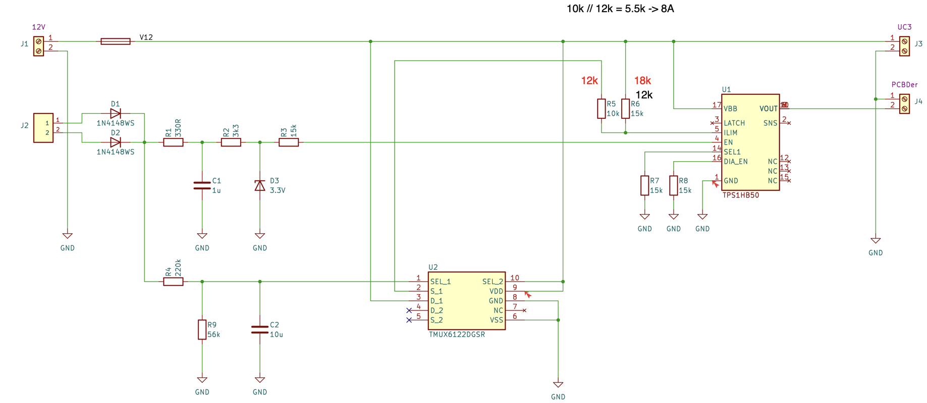
I need to limit the current of two actuators when they are stuck. Typically the nominal current is around 4A, and when the actuators are stuck this raises to 8A our even more. The difficulty is that at startup they will consume a peak current around 10A. So I came up with the following schematics (output to actuators on PCBDer):

Some explanations:

- the two input signals (12V on J2) enable the circuit and trigger a delay on the TMUX,

- initially the TMUX switch is closed hence current limit is provided by R5 in parallel with R6, 18k // 12k allows for a bit more than 12A

- after the delay of ~100ms the TMUX switch opens and current limitation is provided by R6 only, allowing for 5A.

This works quite fine, but it happens that the HB50 burns, and its output si shortcutted when the actuators are stuck. Apparently because the current is too high.

I don't understand why this happens since the circuit is supposed to be protected agains any possible overload or disfunction. 

Any explanation or recommendation ?

  • Hello, 

    Can you explain how you are doing the short to GND test? 

    Its important that this is performed per the "AEC-Q100-012" short condition discussed in section 10.1.6.2 of the datasheet.

    Thank you,

    Sarah

  • Hello Sarah,

    None. I am working on prototypes and have barely a couple of them. Can you explain why/how this could affect the device's thermal protection ?

    Thanks,

    Marc

  • Hi Marc, 

    The AEC-Q100-012 standard is an important method for testing short circuits because, simplified, it insures that you have some amount of impedance on the output. When the short occurs there will be an initial spike in current before the current limit kicks in and stabilizes. If you have no impedance than that initial current spike could be infinite and would inherently burn out the FET. 

    For thermal protection, if you are exceeding any of the datasheet max specifications like voltage you will burn up the FET. AN inductive load can also be tricky. Do you have a significant inductive load on the output? 

    Thank you,

    Sarah Raines

  • Hi Sara, thank you very much for the explanations.

    I indeed have some inductive load since my two actuators are in reality two motors. However, this doesn't seem to be the issue. Let me provide some context:

    Initially I build my prototypes with version A (limited to 10A), this seemed to work quite well, when the actuators are blocked, the current rises quickly (but not instantaneously) and the current limitation kicks in. This limits the amount of power going in the motors and, this is the purposes, avoids them breaking.

    This was on my workbench, and not taking into account that my lab power supply also had some limitation. With a real battery the initial current peak would immediately trigger the current limitation and the motors would simply not be able to startup.

    As a remedy, we found that longer wires would prevent this from issuing, so I finally decided to include a small (typically 0.33 Ohm) resistor in series with the fuse, and that worked out.

    The problem with this resistor is that the steady current of my two motors is ~4A, so the resistor is dissipating ~5W, quite a big resistor finally.

    At this point I decided to replace the TPS with its B version, that is limited to 16A. The thought was that I might spare the power resistor.

    With the 0.33 Ohm resistor this is also working fine, so I decided to try the resistor with a lower values, I tried 0.25 and 0.18 Ohm. Both of the circuits with these lower resistors burned out when the motor is blocked (or at least this is what I believe, the burnout could have happened at startup but I don't really believe that is the case).

    Sorry for the long explanation, maybe it helps you understand where the issue lies.

    Kind regards,

    Marc

  • Hi Marc, 

    1.) Have you used the R_ILIM calculator to determine the right values? https://www.ti.com/tool/download/SLVRBG2

    2.) I cannot pinpoint this 0.33 ohm resistor in series with your FUSE? I am also confused are you saying the resistors burnout or the TPS device burns out? 

    3.) If you have a large inductive load that turns off you can produce significant negative voltage. There is a voltage clamp intenral to the TPS1HB50 part to help with this, but a significant current could still break this clamp. 

    Thank you,

    Sarah

  • Hello Sarah,  sorry for the confusion.

    1) No I didn't use the calculator, but the current limits are OK, since everything works fine with the power resistor at 0.33 Ohm.

    2) You are correct, I added this resistor afterwards, it is simply in series with the fuse.

    3) I understand, but the device does not burn when the load is turned off, but when the current increases above some limit.

    I'll try to summarize:

    When the actuators are started (12V on one of the J2 inputs, the device is enables, initially a current of ~10A is allowed, this is indeed the peak surge current at startup of the actuators, then the TMUX switch closes and current is limited at ~4A. At this point in time the  actuators consume ~2A in normal functioning state. 

    With a series resistor of 0.33Ohm all of this works perfectly fine. When the actuators eventually are blocked, the current rises above 4A and the device will indeed actively limit the current which is the purpose of the design.

    Now, when I reduce the value of the series resistors, the device will burn out when the actuators are blocked. I don't understand what might cause this effect.

    Once again, thanks for your help.

  • Hi Marc, 

    After reviewing the schematic we found an issue with your ILIM. For the HB devices you can only connect a resistor directly to VBB with a very short trace, otherwise you will disrupt the accuracy of the ILIM. Your connection to TMUX is not a viable connection for ILIM. 

    Please refer to the Note in section "9.3.1.2.2 Programmable Current Limit" of the data sheet. 

    Thank you,

    Sarah

  • Hello Sarah,

    You raise an interesting point, however, II don't believe this causes the issue:

    1. If you check the TMUX data sheet you'll see that the maximum capacitance of the output is 5pF, which does not exceed the maximum stated in the HB device as provided in section 9.3.1.2.2.

    2. The burning of the device occurs when the MUX switch is open, hence having even a lower than 2.6pF (max) capacitance, as opposed to the 4.2pF (typical) when the switch is closed.

    3. As I described, the device burn out does not occur at startup when there is a maximum but short inrush current, but when the actuators are blocked which causes the current to raise above 4A to something like 6-8A, but certainly not above the maximum allowable current of the HB device which is 16A.

    3. This does not explain in any way why everything would function perfectly with a 0.33 Ohms resistor in series with the fuse and why the HB burs out when this series resistor is reduced to 0.25Ohm.

    Furthermore in all of the observations I have made, current limitation works perfectly well and is absolutely efficient. I don't believe this is the source of the issue.

  • Hi Marc, 

    The current limit accuracy simply cannot be guaranteed if you are connecting any trace capacitance to the ILIM pin as outlined in the data sheet. 

    Thank you,

    Sarah

  • Sorry, but this does not explain why the device burns and this does not solve my issue. Your explanation is not supported by the specification you cite.

  • Hi Marc, 

    Im sorry. your original question was not understanding how the device would burn out with the given set of protection features. These features rely on the ILIM pin. An inaccurate measurement would not guarantee this performance. 

    Thank you,

    Sarah

  • Hello Sara,

    As I clearly showed, the specifications for the ILIM pin are met as per TI's data sheets, your explanation simply does not hold and is contradicted by experience.

    Furthermore, an inaccurate current limitation does not mean that thermal protection doesn't kick in and that the FET will burn out.

    I appreciate your help but clearly a satisfying answer has not been found.

    Kind regards,

    Marc