This thread has been locked.

If you have a related question, please click the "Ask a related question" button in the top right corner. The newly created question will be automatically linked to this question.

UCC2895: Synchronization Problem

Part Number: UCC2895

Tool/software:

Hello E2E Experts,

Good day.

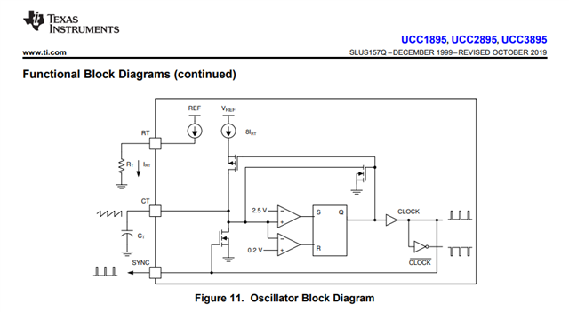
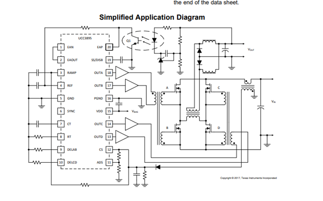
I'm running an UCC2895 with an Rt=56Kohm and Ct=200pF. The clock frequency at Ct is about 625KHz. EAN and EAOUT are connected together. At the output (OUTA to OUTD) I get what is expected : on my oscilloscope connected to OUTA and OUTD I got two square wave that can be shifted changing the EAP voltage.

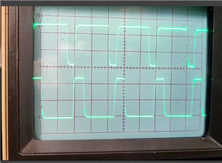
First of all I do not understand why at the SYNC pin I got a waveform as shown below.

I was expecting square pulses because they are coming from a flip flop.

Second, I need to synchronize the UCC2895 with a signal with a frequency of 750 KHz or higher , shaped to have a positive (+3v) pulse of about 7 % duty cycle.

The waveform change immediately to the waveform below and the phase shifting cannot be accomplished anymore by varying the EAP voltage. 

Regards,

TI-CSC

  • Hello,

    Your inquiry is under evaluation.

    Regards,

  • Hello,

    You are correct that the sync pin should have a digital input/output.

    I am wondering if the behavior is due to the CT discharge current that is controlled by the sync pin and your grounding of your PFB.

    Could you check the SYNC, VDD, RAMP, REF with an oscilloscope with the ground of the probes connected directly to pins 5 and 6.

    Also worth mentioning if there is a potential difference between GND (pin 5) and PGND (pin 16) it can also cause the UCC2895 to misbehave.  Make sure these two grounds are connected with trace directly under the IC to remove this possibility.

    Regards,