This thread has been locked.

If you have a related question, please click the "Ask a related question" button in the top right corner. The newly created question will be automatically linked to this question.

BQ25750: Charging current wave

Part Number: BQ25750
Other Parts Discussed in Thread: TPS62135, TPS7A16A-Q1

Tool/software:

Hello TI Team.

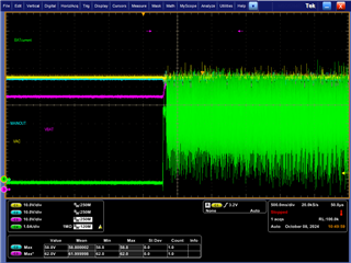
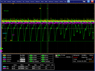
When I charging battery as below setup, I have measured charging current swing it has regular frequency even I turned PFM mode off.

- Input : 55Vdc

- Battery : Li-ion 13S2P (4.2V cell)

- Charging voltage : 53.33V

CC mode & CV mode as same current swing.

* Created: Mon Sep 30 16:20:42 KST 2024
*
* Format: Register Name  tab Character,\t  Register Address  tab Character,\t  Hexadecimal register value.
* BQZ Container: Charger_1_00-bq25750.bqz
*
Charge Voltage Limit	00	10
Charge Current Limit	02	140
Input Current DPM Limit	06	640
Input Voltage DPM Limit	08	348
Reverse Mode Input Current Limit	0A	640
Reverse Mode System Voltage Limit	0C	3E8
Precharge Current Limit	10	48
Termination Current Limit	12	48
Precharge and Termination Control	14	0F
Timer Control	15	0D
Three-Stage Charge Control	16	00
Charger Control	17	D9
Pin Control	18	C0
Power Path and Reverse Mode Control	19	00
MPPT Control	1A	20
TS Charging Threshold Control	1B	96
TS Charging Region Behavior Control	1C	57
TS Reverse Mode Threshold Control	1D	40
Reverse Undervoltage Control	1E	00
VAC Max Power Point Detected	1F	00
Charger Status 1	21	04
Charger Status 2	22	80
Charger Status 3	23	02
Fault Status	24	00
Charger Flag 1	25	00
Charger Flag 2	26	00
Fault Flag	27	00
Charger Mask 1	28	00
Charger Mask 2	29	00
Fault Mask	2A	00
ADC Control	2B	A0
ADC Channel Control	2C	02
IAC ADC - Use Field View	2D	2E7
IBAT ADC - Use Field View	2F	2CA
VAC ADC	31	6A74
VBAT ADC	33	6621
VSYS ADC	35	6A08
TS ADC	37	258
VFB ADC	39	00
Gate Driver Strength Control	3B	00
Gate Driver Dead Time Control	3C	00
Part Information	3D	02
GM Adjust	61	31
Reverse Mode Battery Discharge Current	62	02

Especially, When I supply set to 48V input voltage for charging, It works well and no measure current swing.

I think problem cause there is little difference between the input and the charging voltage.

How I set to stable charging current?

Thank you.

  • Hello Ben,

    Thanks for being patient with this. I'll get back to your question later this week.

    Best Regards,
    Ethan Galloway

  • Hello Ethan

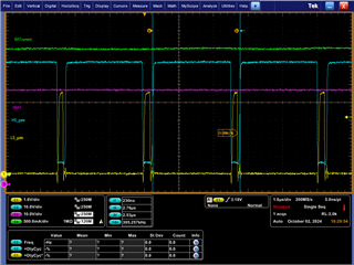
    I measured the Buck FETs gate as below case.

    Case1

    - Input 55V / Charging voltage : 53.3V / max 4A

    - Freq. : 198kHz but, I setted 373kHz(73.2kohm)

    It seems LS gate not enough turn-on time.

    Case2

    - Input 55V / Charging voltage : 53.3V / max 4A

    - Freq. : 395kHz as same setting 73.2kOhm

    - normal behavior but it's better if LS gate turn-on time more.

    For normal Buck operating in the BQ25750, Does it have spec of voltage gap between input and charging voltage?

    Thanks

  • Hello Ben,

    Thanks for the new information. I'm swamped right now and I'll still working on debugging this.

    I have a few questions.

    Do you have an external gate drive supply? Is the ripple improved by adding an external gate drive of about 7V or so?

    If you set ICHG=4A, and set EN_ICHG_PIN=0, does the ripple go away?

    Best Regards,
    Ethan Galloway

  • Hello Ethan

    I set to external gate drive supply using power supply of 7V. And, the Original test board has damaged due to probe gnd pin, I changed test board it has different FB level.

    - Input : 55V / Charging voltage : 57.24V (240K - 6.65K) / Max 4A

    - External gate driver supply : 7V (Power supply is connected to anode pad.)

    - ICHG HW pin set to GND by 6.8K ohm (Target 7A)

    - ICHG SW = 4A

    - EN_ICHG_PIN, I didn't set anything, so it may be 1(reset).

    The result has very large current swing. 

    Thank you in advance.

  • Hello Ben,

    I've got a few more questions to help us debug this.

    How long are the wires to your battery? Long and thin wires may cause stability problems.

    If you put a 1000uF or greater cap on the battery, does the ripple go away?

    Just to confirm, you are using your own board right? Can you send me the most up to date schematics?

    Have you checked your current probe? Sometimes current probes may show an oscillating signal when there isn't one.

    Best Regards,
    Ethan Galloway

  • Hello Ethan

    Sorry I clicked wrong resolved issue button. If you need new ticket, let me know.

    Anyway, your questions answer below for understanding my test and equipment setup.

    <Test setup>

     - Scope : Tek. MSO64B or MSO 5204B

    1) Current probe I am always degaussing before the test. No oscillating issue.

     - VAC supply : ITECH IT6723 (850W, 48V, 10A output setting)

     - MainOut loader : Chroma 63123A (just connected, no load)

     - Battery :

    1) Chroma 62060D-100 Battery simulator (VH58.5V/VL42V/SoC20%/Capa5Ah/DCR0.5/OCP10A). Cable length is under 150cm.

    2) Testing Battey 13S2P for measuring charging cycle. (V_CHG target max : 54.6V). Cable length is under 30cm. 

    3) Target Battery 14S6P not test yet due to this issue. (V_CHG target max : 58.1V)

     - DUT : 

    Yes, I have own board it is more small form factor than your EVkit. As I mentioned other ticket, I missed bootstrap diode. So It needs rework for work.

    The schematic I had uploaded another ticket already, If you need more specific information and photo, let me know your e-mail.

    <Test Result>

    Here is result that comparing gate driver external supply at same DUT condition.

    - Input : 48V

    - Battery : Simulator as upper setting

    - Charging voltage target : 57.24V (240K - 6.65K)

    - ICHG = 4A, set EN_ICHG_PIN=0

    1) Internal gate drive source (REGN)

     - HS gate can not reach to turn-on voltage enough(2.4~2.9V higher). So, LS gate turn on more longer. LS gate turn-on is delayed regularly.

    2) External gate driver supply (7V source from TI TPS62135)

    - HS gate has turn-on voltage (3.6V) and longer time than LS gate. Charging current can be reach to 4A. but it has same issue LS gate turn-on delay regularly.

    My questions

    - 1) If I increase DRV_SUP voltage to 10V, the switching behavior comes better without delay things? because, My FET gate spec as below.

    - 2) Please let me know your circuit parameter for 48V battery test, I want to set my board as your setting.

    Thank you

  • I had set to 9V supply to gate driver, It has same result as 7V. Gate voltage is around 5~5.3V.

    Please let me know debugging point.

    Thank you in advance.

  • Hello Ben,

    Thanks for the new information and thanks for sharing the threshold voltage of your FETs.

    1. The threshold voltage of your FETs is a bit higher than what we have on the EVM. For comparison, the AON6226 FET has a typical threshold voltage of 1.75V. If you swap to a switching FET with a lower VT, does the problem change? A threshold voltage of 3V is going to be difficult for the BQ25750's 5V REGN to drive.

    I think maybe the HS gate drive voltage is falling because the FETs aren't fully turning ON and OFF.

    2. I'll get back to you tomorrow on this test.

    Best Regards,
    Ethan Galloway

  • Hello Ethan

    Thanks you comment.

    It is difficult working FET swap test due to drain pad and via.. also I don't have AON6226. For debugging I will board revision.

    - add bootstrap diode : "V1FM10-M3/H" is applied EV kit already. (Low Vf)

    - change BuckBoost FET : "BSZ070N08LS5ATMA1" has low gate turnon voltage level

    - add external gate drive supply : "TPS7A16A-Q1" has up to 60V input range, output adjustable to 7V setting. Input source is from VAC line.

    If you have any recommended components for debugging, or get the test result, please let me know.

    Thank you.

  • Hello Ben,

    It is difficult working FET swap test due to drain pad and via

    Swapping the FETs is always really difficult. Any FET with a lower VTH should do. A FET like the SiR680LDP, SiR880BDP, or AONS66920 should work.

    Here's the procedure I use when swapping FETs:

    • Use a board preheater to heat the board for about a minute.
    • Use a hot air gun at 800F to heat the board.
    • If the solder isn't melting, slowly turn up the heat on the hot air gun. I often had to use the maximum air flow setting on a hot air gun to get these FETs off. Make sure you don't blow any other components off the board while doing this.

    This will be difficult if you don't have a board preheater or a hot air gun though. You might be able to use 2 soldering irons to melt the solder on the FET's source and drain and lift the FET off the board that way.

    change BuckBoost FET : "BSZ070N08LS5ATMA1" has low gate turnon voltage level

    These FETs should also work

    add external gate drive supply

    For the external gate drive supply, you may not need it after you change FETs. An external gate drive will improve your efficiency though. I've ran your test on the EVM and the EVM works without the need of an external gate drive supply.

    If you have any recommended components for debugging, or get the test result, please let me know.

    For the tests, I have a test procedure that I like to do:

    • At a low VBAT voltage (like 10V), make sure the power path turns-ON and supplies VSYS with VBAT.
    • Test charging at a low voltage with I2C if possible. For example, test charging at 15Vin to 30Vout at 4A.
    • Measure the waveform at the low voltages to make sure HIDRV and LODRV work at that level.
    • Then, do the test at the problem voltage and current level.

    Best Regards,
    Ethan Galloway

  • Hello Ethan

    Thanks your comments. I summarized abnormal switching behavior for more clearly this question.

    1) Bootstrap diode

     - Before : S1G

     - After : V1FM10-M3/H

     - I got the right operating result at 48V input. But It still current swing at 55V input. (Right side)


    2) FET gate threshold voltage (External Gate drive supply)

    - Before : 3.8Vmax

    - After : 2.3Vmax

    - I will test after board revision. I don't have other FETs for replace in my hand.

    3) 55V Input & 57.2V Charging case (Original question in this ticket)

    - I can't fix this switching behavior even I changed diode and added external gate supply.

    Let's see..

    Thank you.

  • Hello Ben,

    Thanks for the quick summary.

    For 3, have you tried a different battery simulator or tried to use an E-load? Some of the equipment I've used before has a current ripple when the power supply is sinking. If it's not a battery/load issue, I think the new FETs may help.

    Best Regards,
    Ethan Galloway

  • Hello Ethan

    I have changed power supply to comparing current ripple at 55V input case, It has same result. I agree with you the new FETs may help. I will update test result after board revision. And this picture I measured Buck(HS gate), Boost(LS gate) at 55V input case. The gate abnormal behavior makes current swing, It has 3.9kHz frequency. Do you have any idea on this frequency?

    Thank you.

  • Hello Ben,

    I'm not sure where that ripple would be from without more information.

    By the way, how are you measuring the HSgate signal?

    Best Regards,
    Ethan Galloway