This thread has been locked.

If you have a related question, please click the "Ask a related question" button in the top right corner. The newly created question will be automatically linked to this question.

BQ79616EVM-021: Teensy 4.1 microcontroller - The IC is in wakeup state but unable to receive data

Part Number: BQ79616EVM-021
Other Parts Discussed in Thread: BQ79616

Tool/software:

We are using Teensy 4.1 microcontroller to communicate with the IC. We have successfully wakeup the IC but we are not able to receive any data through UART communication when sending commands. I have attached our code for your reference below. Can you please tell what the issue in this is and how can we resolve it.

https://e2e.ti.com/cfs-file/__key/communityserver-discussions-components-files/196/bms_5F005F00_testcode.ino

  • Priyangsi,

    You need to set the top of stack before you can get reliable communication.

    If this does not work, a logic analyzer log of the appropriate RX and TX lines would be the most helpful way to debug this issue.

    Regards,

    Ben

  • Benjamin, 

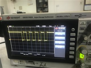
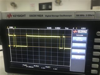
    I have tried the suggested method by declaring the device as both base and top of stack, but still I am not getting any response. Additionally, I also tried by performing single device read/write by taking the default address i.e., 0x00. Please find attached below the software reference and also the data I tried to send observed at the RX pin of the evaluation board. Data at RX pinData at RX pinThe default addressSoftware design reference.

    Please suggest me some other method as I currently dont have an access to a logic analyzer. 

  • Priyangsi,

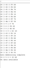
    I noticed the synchronization commands go to 0x34B when they should stop at 0x34A and that you are auto-addressing to three devices but you seem to also indicate there is only one device in the stack.

    Can you have the program print all of the commands that you send to the EVM? Double check that the baud rate and serial protocol are as indicated on the datasheet:

    Additionally, could you check that the TX pin of the EVM actually shows no sign of response? 

    Finally, you can find our reference code here

    Regards,

    Ben

  • Benjamin, 

    I am now using only a single device and I am trying to enable the TSREF output, but I am still getting 0V at the TSREF pin of the evaluation board. I am waking up the IC and then running the command to activate TSREF. Am I missing any steps in between? 

    Also, PFA the code and let me know if there is any problem in this.
    This code is written in Arduino.

    https://e2e.ti.com/cfs-file/__key/communityserver-discussions-components-files/196/Arduino_5F00_Sample_5F00_code.ino

    Regards,

    Priyangsi

  • Benjamin, 

    Additionally I have attached the updated code by implementing the changes suggested by you. The output remains same i.e., no response from the IC. 
    Also, at the TX pin of the IC the voltage is a constant high(4.5V). 

    I also wanted to make sure if we are using a single device is it actually necessary to run these steps (Auto addressing, Syncing DLL loops, Resetting faults).

    https://e2e.ti.com/cfs-file/__key/communityserver-discussions-components-files/196/Arduino_5F00_Code.ino

    Are the below steps necessary for a single device? 

    Regards, 
    Priyangsi

  • Priyangsi,

    Sorry for the delay, I was out of office.

    I have attached a logic analyzer log which you should be able to view with the free program "Logic 2".The log shows a successful auto-addressing and subsequent data reads from a single BQ79616 device using UART. My next best guess as to why you are unable to properly communicate is that during the second set of synchronization commands (the reads to 0x343 to 0x34A) it does not appear you are waiting for the response from the device. 

    Additionally, you do not technically have to set everything as a stack device only to then set the single device as both top of stack and base device. In the sample code that is there to cover both cases of a single device and multiple devices.

    Regards,

    Ben

    https://e2e.ti.com/cfs-file/__key/communityserver-discussions-components-files/196/8424.Communication_5F00_with_5F00_one_5F00_616.sal

  • Benjamin,

    Sorry for the delay. The PARTID was returned correctly after going through the logic analyzer. We were missing the delay while syncing the delay locked loops. Additionally now we are trying to read the cell voltages using the resistor ladder on the Evaluation Board but are not getting the desired response. I am reading the high and low registers of the 16th Cell. Ideally, it should give me the BAT voltage i.e, 24V , but it gives it to be around 12V. Please find the attached code. 
    https://e2e.ti.com/cfs-file/__key/communityserver-discussions-components-files/196/sketch_5F00_oct16a.ino

    In this I am printing the value of the registers and then applying 2s complement and then multiplying by the ADC resolution (190.73uV/LSB). This process I am performing manually. Is there any thing I am missing in the code?. Also if there is anything wrong in the process I am doing manually please let me know. 

    Again thnx, for resolving the previous issue. 

  • Priyangsi,

    I do not see any issue with the code.

    The voltage that the device measures in VCELL16_HI/LO is the voltage between the VC 15 pin and the VC 16 pin. It is not necessarily the BAT voltage. You can check by connecting a voltmeter to the test points to determine what the device is reading and if you are doing your math correctly.

    Regards,

    Ben