This thread has been locked.

If you have a related question, please click the "Ask a related question" button in the top right corner. The newly created question will be automatically linked to this question.

TPS546D24A: Power good signal is restarting

Part Number: TPS546D24A

Tool/software:

Hi,

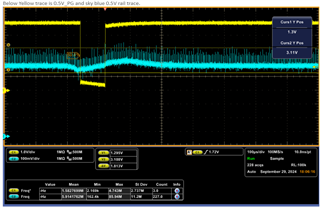
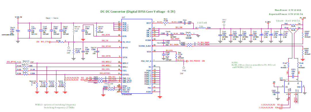
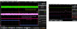
We used the TPS546D24A in our board to convert from 12V to 0.5V, and it was working fine. Then suddenly, the PG signal restarted every 900ms and probed the output voltage, which looked like a small drop (see the image below).

We relaxed under the voltage warning limit from 0.45V to 0.44V, and the PG signal is working fine, consistently high. Is there any limitation that will not provide a low current? Our load is ASIC, and the current is 500mA to 1A at this testing. 

  • Hi Gajendiran,

    The TPS546D24A should be able to support light load or no load without any issues. If you're okay with relaxing the UV threshold, let us know. If you want to know what might be causing that drop, I'll need more information from you.

    For example:

    • When you say it was working fine, and suddenly you start to see PG toggling every 900ms, what changed? How long did it take for this to start happening? Could there be a sudden increase in load that could cause the output voltage to drop? It would be helpful to look at the inductor current.
    • Was there any other fault reported to PMBus other than the VOUT UV warning?
    • I don't think this is related to the issue, but I want to mention that the VSEL pin strapping is set to 0.6V, not 0.5V.

    Thank you,
    Tomoya

  • This is not a light load issue. It looks like the transient current issue.

    We added a 5mohm resistor to measure the load current. The purple trace shows the voltage drop across the 5mOhm resistor. The voltage spike across the 5mOhm resistor is 45mV load for ~100us, which is 9A, and the regulator pulls the PG signal to low.

    What is the maximum transient current this part can support, and for how long? It doesn't seem to support 9A.


  • Hi Gajendiran,

    The device should be able to support a load step of up to its current rating of 40A. To minimize undershoot and overshoot during the load transient, it's important to optimize the loop compensation and power stage design. 

    If you could specify the undershoot and overshoot requirements, as well as the worst-case load step (is it 9A?), I would be able to provide guidance on component selection if necessary.

    Thank you,
    Tomoya

  • Hi Tomoya,

    We are setting the regulator output to 0.5V, and the undershoot and overshoot of 5% of the output voltage, which is 0.475V to 0.525V, are acceptable. The worst-case load step is 15A. We have simulated IR drop for our PCB layout  @36mV drop at 16 A, and the load sense circuit is placed at load.

    The load response in the datasheet is the 30mv drop at 30A. We have seen a similar drop on our board, but we set the under-voltage limit above this dropout voltage, and the PG signal pulled low when the transient happened. Is there a chance to overcome this issue?


    I have one more question, What is this device's minimum enable pin high pulse width threshold?

  • Hello Gajendiran, 

    Tomoya will respond on Monday on the compensation to improve transient response. 

    For your second question regarding high pulse width question on the EN pin,. the device will recognize a High   with the pin going above 1.05V typical (1.1V max) and there is a delay that can be programmed as shown in figure 7.6.

    Thanks 

    Tahar

  •  

    The TPS546D24A  implements a user programmable TON_DELAY and TOFF_DELAY functions.  When programmed to 0ms, TON_DELAY will impose a delay on EN of approximately 100μs. Pulse widths less than TOFF_DELAY - TON_DELAY may be ignored by the device.

    If TOFF_DELAY > TON_DELAY, pulse widths less than 20μs may be ignored. 

  • Hi Gajendiran,

    We are setting the regulator output to 0.5V, and the undershoot and overshoot of 5% of the output voltage, which is 0.475V to 0.525V, are acceptable. The worst-case load step is 15A. We have simulated IR drop for our PCB layout  @36mV drop at 16 A, and the load sense circuit is placed at load.

    The load response in the datasheet is the 30mv drop at 30A. We have seen a similar drop on our board, but we set the under-voltage limit above this dropout voltage, and the PG signal pulled low when the transient happened. Is there a chance to overcome this issue?

    To meet the 5% target requirement (25mV) with a 15A load step, you will need to set the VLOOP Gain to be greater than or equal to 4. Currently, it is set to 2 using Comp Code 8, so you will need to change it to Comp Code 9. However, to switch to Comp Code 9, you will need to either increase the switching frequency or increase the output capacitance.