This thread has been locked.

If you have a related question, please click the "Ask a related question" button in the top right corner. The newly created question will be automatically linked to this question.

TPS92624-Q1: Questions about the Functionality of the LED driver

Part Number: TPS92624-Q1


Tool/software:

Hello,

Question 1)

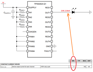
I will supply the Supply pin of the TPS92624-Q1 IC with 5V, I want to use 3 channels in the circuit to drive 9.4mA LEDs (1 LED connected to each output Vled:2.1V)
I want to use the remaining 1 channel to drive a 19.2mA LED (1 LED at output, Vled: 3.5V)
I put a representative schematic below.

In this way, can I use it to drive LEDs with 2 different current values? (Q1.2==> Does it change the answer to my question whether or not to use Rres1, Rres2, Rres3, Rres4?)

Question 2)

I don't plan to use C(OUT1), C(OUT2), C(OUT3), C(OUT4), what kind of problems will I have if I don't use them? What is the advantage of using these capacitors?

Question 3)

If Rres1, Rres2, Rres3, Rres4 are used in the circuit design, will the driving currents of the LEDs change when I increase the supply voltage from 12V to 24V? What I really want to learn is that I want to drive the LEDs with constant current and I don't want it to be affected by the voltage change on the Vsupply pin, is this possible?

  • Hello, I forgot to ask 1 question, please answer this one too

    Question 4)

    There is a situation where I want to drive only 1 LED with only 2.5mA, but the Datasheet says the minimum value is 5mA, is there a way to drive a 2.5mA LED without losing the diagnostic features of the product?

    best regards

  • Hi Ömer,

    1.) I recommend directly connecting all RESx pins to their corresponding OUTx pin instead of leaving them floating. For example, RES2 pin connected to OUT2 pin, etc.  

    In this way, can I use it to drive LEDs with 2 different current values? (Q1.2==> Does it change the answer to my question whether or not to use Rres1, Rres2, Rres3, Rres4?)

    You can select the R(SNSx) resistor values to select the desired current for each channel as per equation 1 of the TPS9264-Q1 datasheet.

    For such low current settings, it is unlikely that including a thermal-sharing resistor would provide much benefit. For example, your 19.2mA channel will only result in ~35mW of internal power dissipation for a supply voltage of 5V.


    2.) The COUTx capacitors provide a low-pass filter at each channel to reduce high-frequency noise. Removing these may affect the linearity of your solution. If you have board space, I recommend including pads for these capacitors that can be populated later if necessary to reduce unwanted noise and improve linearity.

    3.) The constant current output is determined by the V(CS_REG) voltage and the R(SNSx) resistor, see equation 1. The V(CS_REG) voltage is designed to be independent of the supply voltage. 

    4.) The minimum output current per channel is 5mA. Note that the output current per channel is fixed by the R(SNSx) resistor chosen. If you want to reduce the average current through the LED you can use the PWMx pin the reduce the duty cycle.

    For example, you may set the channel 1 output current to 5mA and apply a 50% duty cycle to the PWM1 pin resulting in an average output current of 2.5mA.

    Regards,

    Zach

  • Hello Zach,


    Thank you for your explanatory answers.
    I have one more question: what should I do with the channels I don't use? I'm asking about both INx input and OUTx, RESX.
    (NOTE: I want to continue using the diagnostic features)
    Should I pull the ground or leave it floating?

    best regards

  • Hello Zach,
    Since I will be making several variants, I don't want to use 2 channels in some circuits. In this case, if I don't connect the input current adjustment resistors of the unused 2 channels to the circuit, can I continue to use the diagnostic features of the other 2 channels properly?

    best regards

  • Hi Ömer,

    The PWM pins acts as enable/disable function for the corresponding channels. For unused channels, you can leave the channels open and connect the PWMx pin to ground to disable the channel including diagnostics.

    For your variant control, I recommend placing two 0-Ω series resistors at the PWM pin, one connected to ground and the other connected to your PWM control voltage. You can populate one of these two resistors depending on which channels you want to make active in your variants.

    Regards,

    Zach