This thread has been locked.

If you have a related question, please click the "Ask a related question" button in the top right corner. The newly created question will be automatically linked to this question.

BQ25792: Device not entering PFM mode, going straight to DCM

Part Number: BQ25792
Other Parts Discussed in Thread: BQ25798

Tool/software:

Hi

We've a custom design with a BQ25792 charging a 2S Li-ion pack.

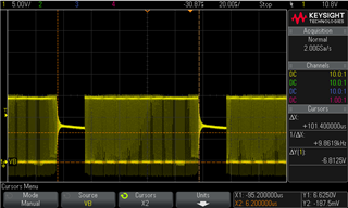
The circuit generally works as expected, we can start and stop charging and vary charge current via I2C. Layout is appears pretty good and switching edges are clean with very minimal ringing. However, the design never seems to enter PFM mode at lighter (~500mA) charging current but instead goes straight to discontinuous mode, even before reducing the inductor on/off ratio significantly. This is despite never changing the default 'enabled' for PFM mode. We can read back "REG12_Charger_Control_3 Register" and confirm it's 0x00. Writing 0x10 to this to disable PFM makes no difference and neither does writing it back to 0x00.

Sometimes we get periods of bursts of DCM mode and then off, which can result in audible (and I'm told very unacceptable) high frequency tones.  

We're (confirmed) switching at 1.5MHz with a 1uH inductor. Decoupling is pretty much as per the reference design, no ship FET or input muxing (power direct to VBUS and AC1/2), and thermistor disabled via REG18 TS_IGNORE bit. 

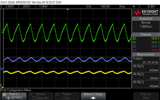
We've tried a real battery packs and a battery emulator, with pack at 6V to 8.4V, and VIN of 11 - 15V.

We've confirmed another PCB behaves in the same way.

Is there anything else that can influence this switchover?

Part code is 0AANLZ8.

  • Hi Jonathan,

    The ceramic capacitors are likely the source of the ringing due to their piezo-electric nature.  Unfortunately, there are still some conditions where the charger enters DCM.  Can you reply with a oscilloscope shot of VBUS, SW1, SYS and if you have a current probe, inductor current, when the noise occurs?  If using an EVM you can desolder the inductor, stand on one edge, solder to one pad and then use a piece a wire to make a loop for the current probe.

  • I haven't had chance to progress this much further yet but can confirm that I have now seen PFM in certain circumstances. For anything other than large charge currents there are periods of no inductor current (DCM) in every cycle, which I guess makes sense to maintain the in:out voltage ratio. Also, I didn't think through the minimum FET on time and quite high switching frequency, which I guess prevents low inductor on:off ratios (without operating frequency reduction).  

    Any ideas why it's 'bursting' operation at ~9.9Khz (plot at SW1)? This is audible. I get that it's probably piezo effect of caps, but why this operation in audio band?

  • Hi Jon,

    At Fsw=1.5Mhz, you are correct that there is a min controllable FET on time at high duty cycle.  Just before entering buck-boost, the PWM control can turn off the FET for a brief time and then turn back on.  This can be in the audible range.  If you lower to fsw=750kHz, does that prevent the noise?  Your VIN to VOUT didn't seem close to max D, though.

    Regards,

    Jeff

  • Hi Jeff,
    I work with Jon - he's out on holiday currently.

    Lowering fsw to 750kHz does not change the frequency of the noise.
    This problem is only visible when the battery is close to full charge (BATP > 8.2V). The voltage on SYS and BATP oscillates between 8.0V and 8.75V with SYS slightly higher and leading in phase. This appears to be switching the BQ25792 between CC and BAT_OVP mode - we see the voltage on BATP rise while the charger is running (and SW1 has switching waveforms) and then fall in PFM mode (presumably as the BAT_OVP discharge resistor being applied). This transition happens somewhere between 2kHz and 10kHz, depending on battery and bus voltage. If this oscillation is above ~4kHz, this does not trigger any interrupt from the charger, if we can slow down the oscillation to around 4kHz, we get interrupts for a state change between CC and CV mode, but never a BAT_OVP fault.

    I'll capture some waveforms and add them here.

    Thanks,
    Dan

  • HI Dan,

    That sounds like the charger is going in and out of recharge with high charge current and/or high ITERM and/or high resistance from BATP to battery pack and/or highly resistive battery pack.  If you lower the ITERM setting and/or VRCH deglitch time or VRCH value in REG0x0A, does the frequency of pulses change?

    Regards,

    Jeff

  • Hi Jeff,
    None of those settings changed anything - we set the register, read it back and dis/enabled charging (using CE pin) between each run to ensure the settings took.


    Tested register values (all tested independently with the other register set back to default):
    REG0A: 0x6A, 0x73, 0x43
    REG09: 0x0A, 0x01

    Thanks,

    Dan

  • Things we have seen make a difference to the oscillation frequency are:
    * Increasing capacitor size on BATP decreased oscillation to around 4kHz (how we saw that interrupts fire and what the state change is at that speed.
    * Increasing the battery voltage closer to 8.45 increases the frequency of oscillation (and decreases the amplitude) until about 8.5V when the oscillation stops and REG1C indicates Charge Termination done

  • Hi Dan, 

    Can you get a scope capture of SYS, BAT and IBAT with current probe?

    Regards,
    Jeff


  • Hi Jeff,
    Traces attached. Green is battery voltage, yellow is SYS and blue is IBAT with positive being into (charging) the battery. VPP is on the measurement screen on the scope trace. Average values for SYS is 8.4V, IBAT is 980mA, VBAT is 8.3V.

    I've done a few more measurements and think it does look to be that the BQ25792 is very sensitive to series resistance between the battery pin and the battery itself. We have a bit of input protection / filtering with a total resistance of around 0.1 ohm. If I bypass this, the battery voltage at which this oscillation starts to appear increases significantly (from around 8.25V to 8.33V) suggesting that this is an artifact of the charger seeing VBAT + I * R and then oscillating when this is enough to trigger CV mode but VBAT alone (in the absence of charging current) results in CC mode being the correct mode.

    One thing worth noting is that I have derived the values for when the oscillation starts using a 2 quadrant power supply which I'm aware is not the best thing as it's unlikely to respond fast enough to keep the voltage stable if we're worried about 10s of kHz. We do still see these oscillations using real batteries - the image above was taken with a real battery and I'm just waiting for one to charge up enough to trigger this behavior with bypass input protection but the PSU is nice to quickly quantify whether this made a difference which it clearly does - reinforcing my theory that this is an ESR related problem.

    Do you have any data on maximum ESR / ESR related ripple allowed for stable operation of the charger? I'll get some data with a real battery shortly. I saw somewhere on this forum that you have a BQ25798 that fixes the charger making audible noise when no battery is present which feels like the same behavior as we're seeing here, just caused by different reasons. Is this part worth consideration (despite not appearing to be easy to get hold of currently)?

    Thanks,
    Dan

  • Hi Dan,

    All of our chargers have a sensitivity to series resistance between the charger battery sense pin (BATP for 79x) and the battery pack. If that resistance x ITERM > recharge threshold, then the charger oscillates in and out of charging until the pack cells complete charging. The fix is to lower ITERM.  The 79x allows for changing VRCH threshold and the deglitch time for determining VRCH. 

    When a battery is attached, the 798 works the same as 792.  If no battery is attached and charge is enabled, the 792 turns off the converter when battery capacitors hit OVP, causing SYS and BAT to collapse, resulting a different oscillation.  798 does not turn off the converter after BAT OVP.

    Regarding your test setup, you can use a regular power supply, an eLOAD set to CV and a >1000uF cap all in parallel to simulate a battery.    

    Regards,

    Jeff

  • Hi Jeff,

    Thanks for your advice on the test setup and alternative part.

    I'm surprised at your comments for the following reasons:
    1) BQ25792 reports itself to be in the CC charge mode constantly rather than CV / done.
    2) The average current going into the battery is oscillating around 1A rather than oscillating between the 200mA default ITERM and 0, agreeing that the ripple is caused by oscillation in/out of the CC charge rather than termination current.
    3) If we put a lot of capacitance on BATP (to slow down the charger noticing this change), it reports that it's oscillating between CC and CV mode.
    3) Adjusting the ITERM parameter, as you previously suggested, did not affect the oscillation frequency.

    I'll replicate your suggested test setup and report what I find.

    Thanks,
    Dan

  • HI Dan,

    Odd. Never seen charge current instability like this. Does the charge flag in REG0x23[7] show that the charge status changed from CC at some point? I assume you have the minimum recommend capacitance after derating at BAT pin and SYS pins?

    Regards,

    Jeff

  • Hi Jeff,
    Correct on the capacitance - 100n + 3x 10u on SYS and 100n + 2 * 10u on BAT with effective capacitance of 12u and 8u respectively once de-rated.

    The charge flag does not indicate the charge status changing which I'm not really surprised at, given that the INT line (which we have setup to interrupt on any change of charge state) isn't triggering. I suspect the analog parts are changing state but this is being de-glitched by the digital part of the charger that handles the registers / interrupt line.

    Thanks,

    Dan

  • Dan, 

    How much capacitance is on BATP?  We only tested with 4S setting and up to 0.047uF.   

    Regards,

    Jeff

  • 470n with 100 ohm series resistor as per datasheet. When I was trying to slow down the feedback to cause interrupts to happen so we could see the state change, I added a 2.2uF in parallel - this produced interrupts at around 4kHz and the BQ25792 registered rapid state changes between CC and CV but this was purely a debugging step.

  • Hi Dan,

    The 470nF on BATP is only recommend when there is a 4S pack.  Not sure you need it but I don't expect it to cause the above issues.  You might try removing it.

    Regards,

    Jeff