BQ25302: EMC issues

Part Number: BQ25302
Other Parts Discussed in Thread: LMR36015

Tool/software:

Hi everyone,
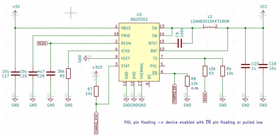
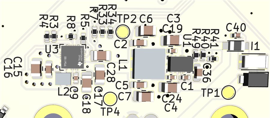
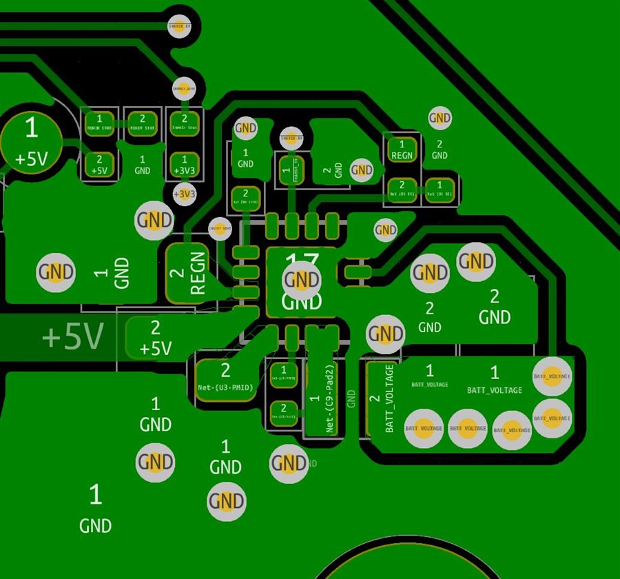
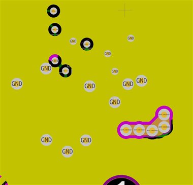
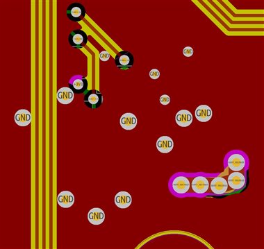
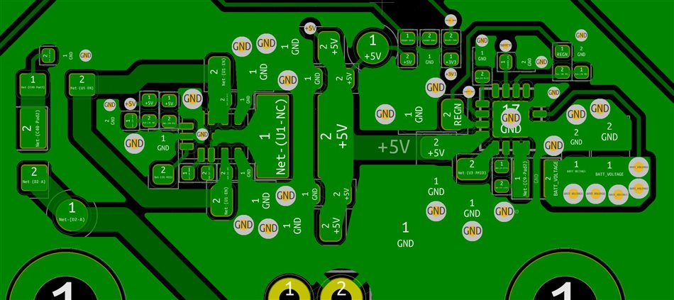
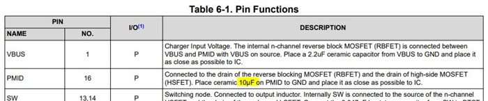
I mounted the BQ25302 charger on a 4-layer PCB. It is a handheld device equipped with a single lithium polymer cell.

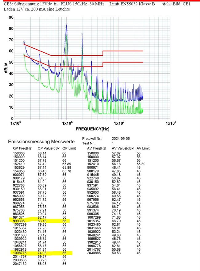
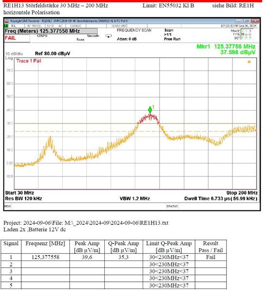
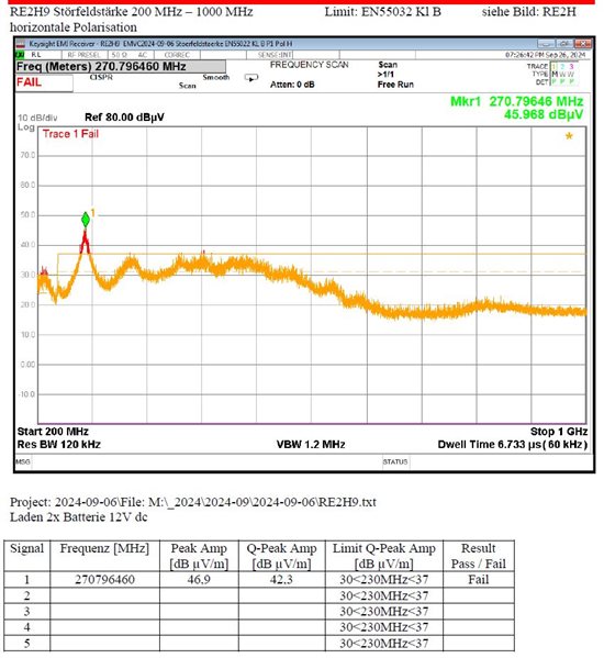
During the usual CE EMC measurements in the lab, I failed the radiation test.
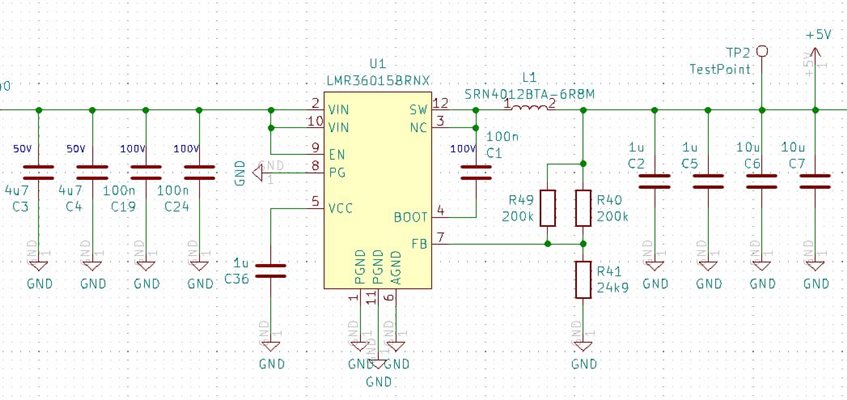
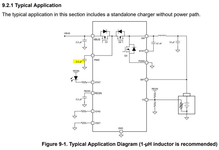
I determined the main cause to be the BQ25302 coil.

Then I tested the evaluation module and noticed that the same problem exists here. (I only had poor measuring equipment available for this comparison measurement)

Does anyone have similar experiences or suggestions for solutions?

  • Hello

    We will review your question and respond as soon as possible.

    Do you have a schematic and layout you can share?

  • Hello Bill, 
    Thank you very much for your efforts. 

    PCB layer structure:    Top - Inner layer 1 - Inner layer 2 - Bottom
    Copper thickness:       4x 2oz
    Inner via diameter:      Small one 0.3mm - Big one 0.5mm    

    The BQ25302 gets the +5V from a LMR36015BRNX. (According to the near-field probe, the coil also causes minor problems.)
    But the main problems come from the BQ25302 coil.

    SCHEMATIC

    Schematic

    IMAGE BOTTOM

    Image Bottom

    LAYOUT BOTTOM (mirrored representation)
    Layout Bottom

    INNER LAYER 2                                                                                              INNER LAYER 1 (GND)

      INNER LAYER 1 (GND) 

    LAYOUT TOP

  • Hi,

    What's the concerned frequency range for EMC?

    Thanks,

    Ning.

  • Wired interference voltage via power supply cable. 
    Peaks at 100 MHz and 200 MHz

    Radiation in the chamber. Peaks at approximately 125 MHz and 270 MHz.  

    Only these two controllers were active during the measurements.

    • BQ25302  (works with 1.2 MHz)
    • LMR36015BRNX  (works with 1 MHz)
  • Here is the switching regulator schematic and layout. From 12V/24V to 5V

  • Hi,

    For BQ25302, REGN cap and BTST cap should be the same values as recommended on the d/s (Figure 9-1. Typical Application Diagram).

    The following actions may be helpful for EMI:
    1)Add 1nF PMID, VBUS, BAT
    Recommend X7R 1nF (0402) which typically has > 300M resonant frequency. Please check with vendor for impedance response.
    The cap on PMID with minimal loop with IC is the top priority.
    2)Use Snubber to reduce EMI
    Snubber (resistor & capacitor) footprint at SW to control EMI source
    Components must be placed closest to SW to be effective
    3)Use shielded output inductors.
    4)The load connection is also very important. An external wider and shorter wire may improve EMI performance.

    For LMR36015BRNX, it is developed by another team. Please submit a separate e2e inquiry and the appropriate group will support.

    Thank you ,

    Ning.

  • Hi Ning, 

    many thanks for the valuable feedback.
    I will test the suggestions and report the results here.

    I have created a separate request for the LMR36015.
    e2e.ti.com/.../lmr36015-emc-issues

    In table 6-1 of the datasheet, a 10 uF capacitor is recommended for PMID. On the other hand, a 2.2 uF capacitor is recommended in the typical application diagrams. If in doubt, I will test both values.

  • Hi,

    The EVM uses 10uF PMID cap.

    Thanks,

    Ning.