This thread has been locked.

If you have a related question, please click the "Ask a related question" button in the top right corner. The newly created question will be automatically linked to this question.

BQ25792: Bq25792 Reading wrong cell count 1S instead of 2S.

Part Number: BQ25792
Other Parts Discussed in Thread: BQ25798, TPS25751

Tool/software:

Hello sir , 

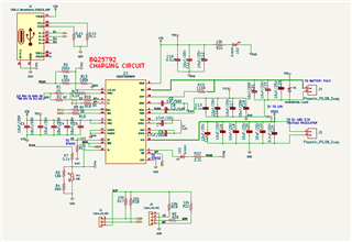
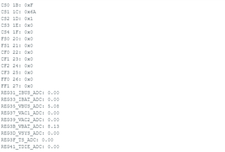
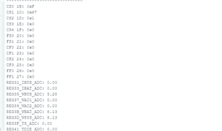
  • I have designed the pcb for bq25792 it was working first but when i decided to increase the input current from (ILim HIz pin) 1.33A to 2A it works for some time around 4 to 5min at that time battery were at 7.8V and then the stat led turned off. Now after debugging Regn pin showing short to gnd. I have changed the ic now the new ic reading wrong cell count . kindly help i am stuck here. And also added to that can i use FTDI based USB to i2c converted for BQ studio ?

  • also i have checked the voltages of other pins Vin is 5.07V , REGN is 5.8V , pmid 0V, TS 3V , why reign is voltage is greater that vin ?

  • Read VBAT: 8.136
    Read Minimal System Voltage: 7.000
    Read Charge Voltage Limit: 8.40
    Read Cell Count: 2
    Read Charge Current Limit: 2.00
    Read Input Voltage Limit: 3.6
    Read Input Current Limit: 1.31
    Read Precharge Voltage Low: 3
    Read Precharge Current: 0.120
    Read Plugged In Status: No
    Read poor source status: Normal
    Read Power Good status: Power good
    Read VAC2 present : VAC2 present (above present threshold)
    Read VAC1 status: = VAC1 present (above present threshold)
    Read Charge Status: Fast Charge
    Read VBUS Status: 3
    Read Battery Present Status: Yes
    Latest readings resoldered ic resolved the issue of 2s battery detection, now all the parameters are correct battery is starting charging stat led glowing when CE pin pulled down but battery is not getting charge, power source detection are okay but plugged in staus coming no
    showing fast charge aslo but charging is not starting

  • Hi Gaurav,

    Can you reply back with all of the status and fault registers REG0x1B-0x27?  Also, can you enable the ADC (REG0x2E[7]) and reply back with the ADC values (REG0x31-0x41))?

    Regards,

    Jeff

  • These are the list of register you have asked.
    
    
    Also i have noticed that when i plugged off the supply STAT LED glowing continuously, REIGN voltage of 5V is present even when supply is disconnected when disconnect battery then regn voltage becomes zero.
  • HI Gaurav,

    The charger is reporting VBUS voltage present and in fast charge.  But the ADC currents and die temp being 0 doesn't make sense.  With ADC enabled, TS pin ADC channel enabled and reading continuously, REGN stays up.

    Can you look at SW2 using an oscilloscope to confirm that the converter is switching?  There should be a square wave on SW2.

    Regards,

    Jeff

  • Yes sure i will do that tomorrow , one more thing i have noticed that their is 4.2V is present across inductor but it should be 5V as of input. does it will affect anything? 

  • Hi Gaurav,

    If there is 4.2V dc across the inductor, then the converter is not switching. The input side of the input should be 5V. The output side is SW2 and should be switching.

    Regards,

    Jeff

  • What will be the issue ? I think main issue is the plugged in status ? How to resolve it? Does lowering frequency to 750KHz will resolve the issue? Have you checked the schematic does anything you can suggest thier?  Also kindly check the gerber file for correction if needed for charging current + System current of 2.5A 2S battery pack does 2 layer board will be fine or i need to go for 4 layer board.

    I need to add one more point here that the circuit were working before at 1.33A Input limit to get the charging current upto 2A i have increased the current first 1.6A works fine after increasing current to 2.2A circuit worked for 4 to 5min and turned off after debugging i have found that regn pin were short to gnd then i changed the ic then that 1s instead of 2s issue occurred and now charging not starting issue may be something in the hardware or layouting going wrong please check and give your valuable feedback . 
    Bq25792.zip
    Total Register Read

    Working module My charger PCB
    I2C REG ADDRESS 0X0 :0X12 I2C REG ADDRESS 0X0 :0X12
    I2C REG ADDRESS 0X1 :0X3 I2C REG ADDRESS 0X1 :0X3
    I2C REG ADDRESS 0X2 :0X48 I2C REG ADDRESS 0X2 :0X48
    I2C REG ADDRESS 0X3 :0X0 I2C REG ADDRESS 0X3 :0X0
    I2C REG ADDRESS 0X4 :0XC8 I2C REG ADDRESS 0X4 :0XC8
    I2C REG ADDRESS 0X5 :0X24 I2C REG ADDRESS 0X5 :0X24
    I2C REG ADDRESS 0X6 :0X0 I2C REG ADDRESS 0X6 :0X0
    I2C REG ADDRESS 0X7 :0X84 I2C REG ADDRESS 0X7 :0X84
    I2C REG ADDRESS 0X8 :0XC3 I2C REG ADDRESS 0X8 :0XC3
    I2C REG ADDRESS 0X9 :0X5 I2C REG ADDRESS 0X9 :0X5
    I2C REG ADDRESS 0XA :0X63 I2C REG ADDRESS 0XA :0X63
    I2C REG ADDRESS 0XB :0X0 I2C REG ADDRESS 0XB :0X0
    I2C REG ADDRESS 0XC :0XDC I2C REG ADDRESS 0XC :0XDC
    I2C REG ADDRESS 0XD :0X4B I2C REG ADDRESS 0XD :0X4B
    I2C REG ADDRESS 0XE :0X3D I2C REG ADDRESS 0XE :0X3D
    I2C REG ADDRESS 0XF :0XA2 I2C REG ADDRESS 0XF :0XA2
    I2C REG ADDRESS 0X10 :0X85 I2C REG ADDRESS 0X10 :0X85
    I2C REG ADDRESS 0X11 :0X40 I2C REG ADDRESS 0X11 :0X40
    I2C REG ADDRESS 0X12 :0X0 I2C REG ADDRESS 0X12 :0X0
    I2C REG ADDRESS 0X13 :0X1 I2C REG ADDRESS 0X13 :0X1
    I2C REG ADDRESS 0X14 :0X16 I2C REG ADDRESS 0X14 :0X16
    I2C REG ADDRESS 0X15 :0XAA I2C REG ADDRESS 0X15 :0XAA
    I2C REG ADDRESS 0X16 :0XC0 I2C REG ADDRESS 0X16 :0XC0
    I2C REG ADDRESS 0X17 :0X7A I2C REG ADDRESS 0X17 :0X7A
    I2C REG ADDRESS 0X18 :0X54 I2C REG ADDRESS 0X18 :0X54
    I2C REG ADDRESS 0X19 :0X0 I2C REG ADDRESS 0X19 :0X0
    I2C REG ADDRESS 0X1A :0X84 I2C REG ADDRESS 0X1A :0X84
    I2C REG ADDRESS 0X1B :0X8F I2C REG ADDRESS 0X1B :0XF
    I2C REG ADDRESS 0X1C :0X6C I2C REG ADDRESS 0X1C :0X6C
    I2C REG ADDRESS 0X1D :0X1 I2C REG ADDRESS 0X1D :0X1
    I2C REG ADDRESS 0X1E :0X0 I2C REG ADDRESS 0X1E :0X0
    I2C REG ADDRESS 0X1F :0X0 I2C REG ADDRESS 0X1F :0X0
    I2C REG ADDRESS 0X20 :0X0 I2C REG ADDRESS 0X20 :0X0
    I2C REG ADDRESS 0X21 :0X0 I2C REG ADDRESS 0X21 :0X0
    I2C REG ADDRESS 0X22 :0X0 I2C REG ADDRESS 0X22 :0X0
    I2C REG ADDRESS 0X23 :0X0 I2C REG ADDRESS 0X23 :0X0
    I2C REG ADDRESS 0X24 :0X0 I2C REG ADDRESS 0X24 :0X0
    I2C REG ADDRESS 0X25 :0X0 I2C REG ADDRESS 0X25 :0X0
    I2C REG ADDRESS 0X26 :0X0 I2C REG ADDRESS 0X26 :0X0
    I2C REG ADDRESS 0X27 :0X0 I2C REG ADDRESS 0X27 :0X0
    I2C REG ADDRESS 0X28 :0X0 I2C REG ADDRESS 0X28 :0X0
    I2C REG ADDRESS 0X29 :0X0 I2C REG ADDRESS 0X29 :0X0
    I2C REG ADDRESS 0X2A :0X0 I2C REG ADDRESS 0X2A :0X0
    I2C REG ADDRESS 0X2B :0X0 I2C REG ADDRESS 0X2B :0X0
    I2C REG ADDRESS 0X2C :0X0 I2C REG ADDRESS 0X2C :0X0
    I2C REG ADDRESS 0X2D :0X0 I2C REG ADDRESS 0X2D :0X0
    I2C REG ADDRESS 0X2E :0X88 I2C REG ADDRESS 0X2E :0X88
    I2C REG ADDRESS 0X2F :0X8E I2C REG ADDRESS 0X2F :0X8E
    I2C REG ADC 0X31 : 0.00 I2C REG ADC 0X31 : 0.00
    I2C REG ADC 0X33 : 623.00 I2C REG ADC 0X33 : 0.00
    I2C REG ADC 0X35 : 5164.00 I2C REG ADC 0X35 : 5105.00
    I2C REG ADC 0X37 : 0.00 I2C REG ADC 0X37 : 0.00
    I2C REG ADC 0X39 : 0.00 I2C REG ADC 0X39 : 0.00
    I2C REG ADC 0X3B : 8307.00 I2C REG ADC 0X3B : 8000.00
    I2C REG ADC 0X3D : 0.00 I2C REG ADC 0X3D : 0.00
    I2C REG ADC 0X3F : 0.00 I2C REG ADC 0X3F : 0.00
    I2C REG ADC 0X41 : 0.00 I2C REG ADC 0X41 : 0.00
    I2C REG ADC 0X43 : 0.00 I2C REG ADC 0X43 : 0.00
    I2C REG ADC 0X45 : 0.00 I2C REG ADC 0X45 : 0.00
    I2C REG ADC 0X47 : 8.00 I2C REG ADC 0X47 : 8.00
  • Hi Gurav,

    I do not see any obvious errors with the schematic above; however, the schematic in the zip has BATP unconnected which could result in the issues you are seeing. Is BATP connected to BAT through a resistor? Can you confirm that /CE =GND and ILIM_HIZ pin is NOT at GND?  The registers look correct.  The gerber shows that you did not follow the recommend board layout, specifically the two 0.1uF caps from PMID to GND and SYS to GND were not placed on top of the IC.  This should not prevent the charger from switching but can result in reduced charge current.

    Regards,

    Jeff

  • Hi jeff F,
    Yes Batp is connected to bat through resistor of 100R and CE is connected to GND IC turning stat LED ON after CE connected to GND and voltage measured at ILIM_HIZ pin is 2V. About capacitor of PMID and SYS my 2layer pcb limited me to do that.

  • Hi Gaurav,

    Were you able to confirm with oscope that the converter is not switching by looking at the SWx nodes?  If not, I suspect the inductor or BTST caps are not soldered correctly.  Or the installed BTST caps are not 47nF.

    Regards,

    Jeff

  • Okay , I will check that tommarrow and confirm. 

  • Hey Jeff F,
    You were absolutely write thank you so much , In my inventory box 47nF cap was not  47nF. mounting 47nF solved the issue , I am really sorry for this .
    1) I just have a few question according to my charger gerber file do you think i can go for at least 2A current or i need to go for four layer pcb , two layer is not sufficient and it will generate problem or heating ?
    2) I have done the charging test battery charging okay but IC not terminating the charging process when battery pack voltage is 8.41V i can see it on register , ic still reporting fast charging & pumping 0.5A current to the battery EN_TERM enable but charger not terminating charging even if battery reaches to 8.4V-8.42V .  
    3)Can i operate the Ic always in buck mode to reduce heating by putting PD voltage to 9V ? 
    4)Also i have trying to increase the input current but it is not increasing after 1.6A (at that time battery charging current is 0.78A) my ILim_Hiz pin voltage is 2.5V. if i write cmd from i2c to increase input current upto 2A then output power disconnects my input source is of 33W and supports PD protocol 5V 3A it can produce.

  • please reply

  • HI Gaurav,

    Regarding 1, other customers have successfully used 2 layer PCB up to 2A.  The IC will likely get hotter than it would on a 4 layer board with internal GND for heatsinking.  

    Regarding 2, the charger only terminates if V(BAT)=VREG and I(BAT), as measured through internal BATFET <ITERM, and the charger is not in IINDPM (reduced input current ), VINDPM (regulated VBUS to clamp input current), thermal regulation or supplement mode for load on SYS.  I assume you do not have a load directly connected to BAT that is adding to ITERM.  Also, you can try enable or disabling PFM.  With VBUS close to VBAT, we have found that enabling PFM generally allows for termination.  If you still can't terminate, I recommend using the ADC IBAT measurement to let the host decide when to terminate.

    Regarding 3, yes.

    Regarding 4, the host can disable the ILIM_HIZ clamp by setting REG0x14[1]=0.  Then it can increase the input current limit in REG0x06-07.  

    If your layout does not place the 0.1uF caps for PMID and SYS to GND on top of the IC, which requires SWx to be via'd down under the IC to the inductor, the switching noise may reduce max charge current.

    Regards,

    Jeff

  • Hi jeff F thank you for your reply,
    I really like to know that and please correct me if i am wrong ,
    1) The CC1 and CC2 pins are required for pd voltage negotiation to 9V / 12V right now it is 5V because i have connected 5.1K to gnd from both the pins. 
    2) If yes for question 1 then how can i archive 9V input selection for my bq25792 board or it requires separate pd ic? suppose i am able to select 9V input then what will be my max input current limit ? 
    3) What are the ic we can use for then please suggest smaller package and will not take much space. 

  • Hi Gaurav,

    Regarding 1 and 2, you need a separate pd communication IC.

    Regarding 3, TPS25751 is a port controller.  We have an EVM with both TPS25751 and BQ25798 https://www.ti.com/tool/USB-PD-CHG-EVM-01.

    Regards,
    Jeff

  • Jeff F
    Sorry to say this but i really want compact ic around 8pin package and will have smaller component count . Do you think ch224k ic will work or any other ic will support?  If TI has this type of ic please suggest.

  • Hi Gaurav,

    I am not familiar with TI's USB products.  I recommend you submit another ticket asking for similar part to ch224k.

    Regards,

    Jeff