This thread has been locked.

If you have a related question, please click the "Ask a related question" button in the top right corner. The newly created question will be automatically linked to this question.

BQ25620: About the trickle current

Part Number: BQ25620

Tool/software:

Hi Sir,

My customer is testing the trickle charger current.
Therefore, the battery is forced to be at OV,
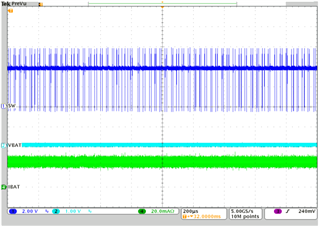
But it was found that trickle charger current is unstable.
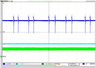
The design value of LC of our circuit refers to spec, 1uH & 20uF,
Later we added 22uF on the output side (VSYS),
Only in this way can trickle current become stable.
Could you please help explain the reason?
Please refer to the attached file for the waveform.

BQ25620 trickle charging current issue 1007_2.xlsx

  • Hi Henry, 

    Please see my comments below. 

    I have attempted to replicate the observed behavior from the attachment, but am unable to do so testing with the BQ25620EVM which has 1uH inductor and 20uF at SYS pin populated. 

    In my lab testing charge current remains stable at approximately 20mA. Can you please help to request customer to share a register dump of all their register setting? Also do they have any load connected at SYS during their test? 

    Best Regards,

    Garrett 

  • hi , Garrett

    Thanks for you reply,

    In our test, register was not changed,
    Therefore, it operates with the default setting.
    We disconnected the subsequent device,
    Therefore, only the charger IC and its peripherals are tested during testing.
    We have only tested this PCB to charge the battery from the SYS pin by external power supply.

    thanks.

    Dylan,

  • Hi Dylan, 

    Thank you for clarifying your test setup and verifying no registers are modified. 

    Below are my test results with BQ25620EVM. As you can see there is no indication of charge current instability when in trickle charge. 

    CH1 (blue) = SW; CH2 (light blue) = VBAT; CH4 (green) = Ibat 

    -200us/div

    -20us/div

    Where are you measuring trickle current on your board? is it on the input side or the output side of the BQ25620 device? When operating at such low output current some ripple is expected on the input current draw because converter is operating in PFM (pulse frequency modulation) mode rather than PWM mode.

    Best Regards,

    Garrett

  • h, Garrett:

      thanks for your reply.

     I test charging current current from BAT pin to battery.pack.

    and I have 3 questions.

    1. What causes charging current instability?
    2. What is the safe design value of Cout in our design ?
    If the battery is charged from the SYS pin external power supply (4.4V/1.5A) through the internal power path, will there be any impact on the IC?

    Thanks.

    Dylan

  • Hi Dylan, 

    Thank you for your answers. Please see my comments below. 

    1) At this point in time I cannot say. It is not expected and we are unable to observe the same instability testing BQ25620 in our lab. Are you sure the provided current waveform is taken at BAT pin? In my testing I can observe similar current waveform at VBUS input, but as the waveforms above show I observe no instability at output of BAT pin. 

    Does the same ICHG current instability exist if you test with a higher battery voltage still in the trickle charge range such as 1V VBAT? Is the battery voltage stable during the time when current instability is observed? 

    2) TI recommends a minimum of 20uF and a maximum of 500uF capacitance at SYS pin, which is converter output.

    3) As discussed in previous E2E thread (linked below) the device is not designed to charge from external power supply at SYS. Device performance cannot be guaranteed when used in a way it was not designed for. TI does not recommend attempting to charge the battery from external power supply at SYS.

    https://e2e.ti.com/support/power-management-group/power-management/f/power-management-forum/1406479/bq25620-some-questions 

    Best Regards,

    Garrett