This thread has been locked.

If you have a related question, please click the "Ask a related question" button in the top right corner. The newly created question will be automatically linked to this question.

LM3409-Q1: LM3409-Q1

Part Number: LM3409-Q1
Other Parts Discussed in Thread: LM3409

Tool/software:

Hi,

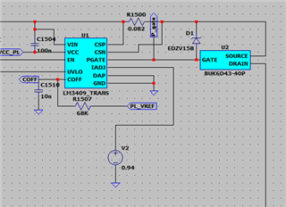
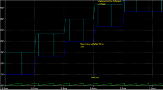
Iam using LM3409 model for constant current drive, i have set the current for 2.4A, the COFF time as per calculation and measurement is different, can i know in simulation which signal i need to measure exactly, for Coff measurement,i have measured the OFF time of PMOS switching (Gate input).

We are looking forward your quick response.

Thanks and Regards,

Sethilkumar

  • Hello Sethilkumar,

    Yes that is the correct signal to measure, assuming you are measuring the amount of time the gate input voltage is low not high (PMOS). If you provide your schematic and calculations I can help to review to see if there are any errors. 

    Thanks,

    Jaron

  • Dear jaron

     My Roff 68K ohm and coff 10nF and applying 5v constant at coff pin, 

    but in my situation, both in input voltage variation as well as output load current variation toff is varying.

    i have shared my circuit for your ref.

    thanks 

    regards

    senthil

  • Dear Jaron,

                 As we discussed her by iam sharing the results of my circuit, iam getting variations in my Coff time with input voltage variations, can you please help us in this 

    Roff =68K, coff=10nF, iam applying constant 5v to the Roff and coff there is no feedback,

    1. iam applying variable input voltage from 9V to 26V (Step voltage of 9V, 14V,18V, 22V, 26V) but laod 2.3A constant at this condition frequency as well as Coff time is also varying.

    my question is will coff time vary or it should be constant.

    output wave forms shared for your ref.

  • Hi Senthil,

    Coff time is only constant when it is referenced to Vout. If your Coff pin is referenced to a constant 5V supply your Coff time and thus peak to peak ripple will vary.

    Thanks,

    Jaron

  • Hi Jaron 

                   Thanks for your information, about Coff timing ,i have few more doubts needs to be clarified

    1.RSNS i have calculated 0.0820 ohms, so it will be set to maximum current of 3A as per the formula correct, is RSNS is current setting resistor (maximum limit).

    2.can i apply constant voltage 0-1.24V to IADJ pin, or we need to use any RC combination to this pin. iam applying 1.015V to the iadj pin constant without any RC.

    3.is COFF pin and IADJ pin both have any relation with PWM switching in PMOS gate voltage.

    4.what is the maximum current consumption of COFF pin.

    i have shared my schematic for you reference

    ...

    Thanks 

    Senthil

  • 1. Yes Rsns is the current setting resistor and your calculation is correct. 

    2. A 0.1 µF capacitor connected from the IADJ pin to GND is recommended when using this method. It may also be
    necessary to have a 1kΩ series resistor with the capacitor to create an RC filter. The filter will help remove high
    frequency noise created by other connected circuitry.

    3. There are two methods to PWM dim. Method 1: Apply an external PWM signal to the EN terminal, this method is unrelated to COFF or IADJ simply supply a PWM signal to the EN pin, logic low (below 0.5V) at EN will disable the internal driver and shut off the current flow to the LED array. Method 2: External Parallel FET, in this method a small diode an additional resistor are connected in series with the off time resistor as shown in the figure below. This method is covered in depth in section 8.3.8 of the datasheet.

    4. Typical current consumption for that pin is not specified although I can tell you that it is very low, in the nA range. The absolute maximum continuous current rating for that pin is +/- 1 mA, but as I said the typical value should be much lower than that.

    Thanks,

    Jaron