This thread has been locked.

If you have a related question, please click the "Ask a related question" button in the top right corner. The newly created question will be automatically linked to this question.

BQ25672: BQ25672 short circuit after start charging

Part Number: BQ25672

Tool/software:

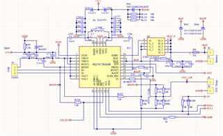
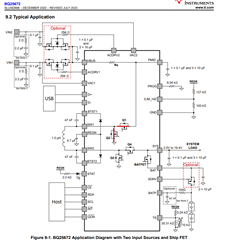
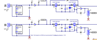
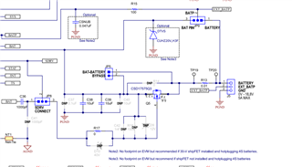
I built the system as in the diagram. Unfortunately, the BQ25672 system is damaged by an internal short circuit after switching on the charging. I damaged 13 pieces of BQ25672 in this way. I built two separate prototypes and both damages the same way.

Uin = 21Vdc
Icharge = 1A

Final configuration 4S (4x4,1V)

Tests I performed:
When shorting /CE to ground:

for Rprog = 27k (4S) the system is damaged immediately
for Rprog = 13.5k (3S) the system works correctly, but is damaged after several quick short circuits /CE to ground
for Rprog = 8.2k (2S) the system works correctly without damage after a large number of short circuits /CE to ground.

During operation, the charging current = 1A, the voltages are also correct.

The damage also appears after switching on the charging by connecting the NTC thermistor. It does not matter whether charging is switched on by shorting /CE or connecting an NTC thermistor.

After damage:
Q1, Q2 - shorted

Q4, Q4, BATFET - ok (~ 0.5V on the MOSFET diode)
resistance:
SW1 - PMID - 7 mohm
SW1 - GND 13 mohm
GND-PMID - 27 mohm

What could be causing the damage?

  • Hi Pawel,

    Do you have an input snubber from 2ohm, 2.2uF as shown on EVM below:

    Hot plugging >15V power supply can result in inductive ringing >30V max input voltage, which damages the chip.

    Also, with 4S battery, you need similar protection for BAT and BATP pins 

    Regards,

    Jeff

  • Thank you Jeff for your answer.

    I do not have a snubber (2R + 2.2uF) at the board input, only 2x 22uF + 100nF MLCC + Zener diode 24V 3W 1SMB5934BT3G. I powered it directly from Hameg HMP4040.

    The damage to the system occurred after switching on the charging by connecting the /CE input to GND or connect NTC. The supply voltage was constantly connected.

    TVS diodes to BAT and BATP are connected (D42, D44), 47n also (C51)

  • Hi Pawel,

    The damage is likely overvoltage.  Did following recommend layout in the datasheet and EVM user's guide?  This layout minimizes ringing on the SW nodes.  Do you have oscillscope to look at the SWx nodes when operating at a lower voltage?  If there is ringing on the SWx nodes at lower voltage, it will only get worse at higher voltages. 

    I am unable to access your google drive.  Can you send me a pdf of your schematic?

    Regards,

    Jeff 

  • My PCB is a bit different, because it's just a two-layer PCB. But the distances between the IC and the capacitors are also very small. After the weekend I'll get a new batch of ICs and then I'll check the voltage waveform on the SW pins.