A related question is a question created from another question. When the related question is created, it will be automatically linked to the original question.
If you have a related question, please click the "Ask a related question" button in the top right corner. The newly created question will be automatically linked to this question.
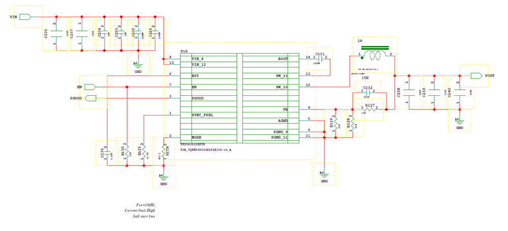
Recommend R126 (MODE), R125 (FSEL), R129,R128 (ls fb) and C230 (BP5) connect to AGND, instead of GND.
Connect AGND to PGND at one point. See figure 8-32 in TPS543620 datasheet page 31 link for example schematic. a zero resistor can be substituted for the net tie.
See figure 10-1 in datasheet for example pcb layout showing the agnd island and connection to pgnd and placement of vin to pgnd capacitors.
Consider adding a 0 zero ohm resistor in series with C232 (boot). Depending on PCB layout a 2.2Ohm resistor may be required to reduce SW node voltage overshoot.
Recommend adding a 0-Ohm placeholder for an Rff in series with C232 . This can help improve load regulation in case of non-ideal AGND to PGND connection in the PCB layout.
With TPS543620 Rmode can be 26.7kohm for the lower current limit setting. Make use the inductor saturation current is greater than current limit.
The TPS543320 is the 3A version of TPS543620, if TPS543320 used, use Rmode of 2.21kohm